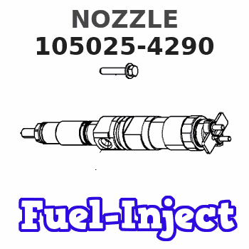
Information nozzle
BOSCH
9 432 612 953
9432612953
ZEXEL
105025-4290
1050254290
Rating:
Compare Prices: .
As an associate, we earn commssions on qualifying purchases through the links below

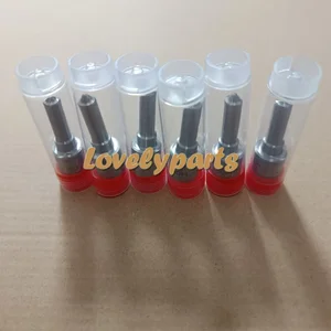
105025-4290 Fuel Injection Nozzle 6Pcs
DFGUFG [Product compatibility]: The OE number of this product is 105025-4290 || [Enhanced Fuel Efficiency & Power Output: Precision-engineered fuel injectors optimize spray patterns for improved combustion efficiency, directly boosting mileage while maintaining stable engine performance across all RPM ranges || [Easy to install and affordable]: Each fuel injector meets factory standard specifications, is simple and convenient to install, has higher combustion efficiency, and can effectively reduce fuel consumption || [High-quality materials for better performance]: The injectors are made of high-quality materials and advanced manufacturing processes to ensure durability and service life, allowing your engine to run smoothly for a long time || [Guaranteed Engine Performance]: This product is one of the key components of electronic fuel injection engines, helping to improve engine performance
DFGUFG [Product compatibility]: The OE number of this product is 105025-4290 || [Enhanced Fuel Efficiency & Power Output: Precision-engineered fuel injectors optimize spray patterns for improved combustion efficiency, directly boosting mileage while maintaining stable engine performance across all RPM ranges || [Easy to install and affordable]: Each fuel injector meets factory standard specifications, is simple and convenient to install, has higher combustion efficiency, and can effectively reduce fuel consumption || [High-quality materials for better performance]: The injectors are made of high-quality materials and advanced manufacturing processes to ensure durability and service life, allowing your engine to run smoothly for a long time || [Guaranteed Engine Performance]: This product is one of the key components of electronic fuel injection engines, helping to improve engine performance
You can express buy:
USD 44.7
19-05-2025
19-05-2025
6Pcs Injector Nozzle 105025-4290 DLLA150S325ND117 for Hino Ribbon EM100 MU10
Cross reference number
Zexel num
Bosch num
Firm num
Name
Information:
1. Remove bolts (1) and the washers that hold rocker shaft assembly (2) in position.2. Remove rocker shaft assembly (2). Remove the O-ring seal from the rear rocker arm support bracket.3. Put identification marks on push rods (3) as to their location in the engine. Remove the push rods.Install Rocker Shaft Assembly & Push Rods
1. Install push rods (1). Make sure they are in their original location in the engine and in position in the valve lifters.
Loosen the adjusting screws on the rocker arms. This will prevent a bent valve or push rod during installation of the rocker shaft assembly.
2. Install a new O-ring seal in the rear rocker arm support bracket. Put 2P2506 Thread Lubricant on all of the bolts that hold the rocker shaft assembly in position except for the bolt that goes through the rear rocker arm support bracket.3. Put rocker shaft assembly (2) in position on the engine. Make sure the dowels in the support bracket are in alignment with the dowel holes in the cylinder head. Make sure the rocker arms are engaged with the push rods.4. Install the bolts and washers that hold the rocker shaft assembly in position. Tighten them until they are finger tight.
3304 Engine Sequence
3306 Engine Sequence5. Tighten the bolts that hold the rocker shaft as follows:a. Tighten the bolts in number sequence to a torque of 156 N m (115 lb ft).b. Tighten the bolts in number sequence to a torque of 250 17 N m (185 13 lb ft).c. Tighten the bolts again in number sequence to a torque of 250 17 N m (185 13 lb ft).6. See "Valve Clearance Setting" in Testing & Adjusting. Make an adjustment to the valves so the intake valves have 0.38 mm (.015 in) clearance and the exhaust valves have 0.64 mm (.025 in) clearance. Tighten the locknuts for the adjusting screws to a torque of 29 7 N m (21 5 lb ft).End By:a. install valve cover