Information nozzle
BOSCH
9 432 610 918
9432610918
ZEXEL
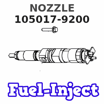
105017-9200
1050179200
NISSAN-DIESEL
16620Z5673
16620z5673
Rating:
Compare Prices: .
As an associate, we earn commssions on qualifying purchases through the links below

The injector DSLA153PN920 DLLA145PN382DLA152PN381 diesel engine fuel injector auto parts are of - (Color: DLLA145PN382)
Generic Color: DLLA145PN382
Generic Color: DLLA145PN382

$76.89
07 Jul 2021
CN: EMIAOTO
EMIAOTO 4 Pcs DLLA152PN232 DLLA145PN382 DLLA147PN252 DLLA156PN262 Injector Nozzle for Bobcat Kubota Zexel Engine DLLA152PN381 DSLA153PN920 DLLA146PN968
EMIAOTO OEM Part Numbers:DLLA152PN232 DLLA145PN382 DLLA152PN381 DSLA153PN920 DLLA146PN968 DLLA147PN252 DLLA156PN262 || Fit for:Bobcat Kubota Zexel Engine || Conditions: new and high quality. The product is the same size as the original part, and the replacement is simple. || One year warranty, shipped within 1-2 days and delivered to you within 10-20 days || We refund or reship for non-received items that is over our estimate shipping time for free
EMIAOTO OEM Part Numbers:DLLA152PN232 DLLA145PN382 DLLA152PN381 DSLA153PN920 DLLA146PN968 DLLA147PN252 DLLA156PN262 || Fit for:Bobcat Kubota Zexel Engine || Conditions: new and high quality. The product is the same size as the original part, and the replacement is simple. || One year warranty, shipped within 1-2 days and delivered to you within 10-20 days || We refund or reship for non-received items that is over our estimate shipping time for free
$66.00
07 Jul 2021
CN: Tapeak
Tapeak 4 Pcs Injector Nozzle DLLA147PN252 DLLA156PN262 for Bobcat Kubota Zexel Engine DLLA152PN232 DLLA145PN382 DLLA152PN381 DSLA153PN920 DLLA146PN968
Tapeak Part Numbers:DLLA152PN232 DLLA145PN382 DLLA152PN381 DSLA153PN920 DLLA146PN968 DLLA147PN252 DLLA156PN262 || Condition: 100% NEW and high quality || Fit for:Bobcat Kubota Zexel Engine || The same dimensions as the original factory replacement part and easy to install || One year warranty and delivery to you in 10-15 days
Tapeak Part Numbers:DLLA152PN232 DLLA145PN382 DLLA152PN381 DSLA153PN920 DLLA146PN968 DLLA147PN252 DLLA156PN262 || Condition: 100% NEW and high quality || Fit for:Bobcat Kubota Zexel Engine || The same dimensions as the original factory replacement part and easy to install || One year warranty and delivery to you in 10-15 days
Cross reference number
Zexel num
Bosch num
Firm num
Name
105017-9200
16620Z5673 NISSAN-DIESEL
NOZZLE
A 50LD NOZZLE N (DLLA-P) N
A 50LD NOZZLE N (DLLA-P) N
Information:
* Be sure to orient the oil grooves as indicated above, otherwise seizures may occur in the engine.
* Use oversize thrust plates when adjusting the crankshaft end play. The upper and lower thrust plates on the same side must be of the same size. The thrust plates on one side may differ in size from those on the other side. Installation: Main bearings
* The upper main bearing has an oil hole while the lower main bearing does not. Do not confuse the two, as incorrect installation can cause seizures in the engine.
* Select and use a main bearing set of a thickness that can accommodate the inside diameter of each main bearing fitting hole between the upper crankcase and lower crankcase and the diameter of the corresponding crankshaft journal. Select the appropriate main bearing set by one of the two following methods.(1) Measurement based selection* Mount the upper crankcase on the lower crankcase without fitting main bearings. * Tighten the main cap bolts to 20 N m {2.0 kgf m}.* Measure the inside diameter of the main bearing fitting hole between the upper crankcase and lower crankcase (vertically from one point), and the diameter of the crankshaft journal (vertically or horizontally from one point).* Select a main bearing set that matches the measurements from the table below. If the color identification mark is indiscernible, measure the thickness of the bearing walls and use the measurements in its place. (Unit: mm) (2) Color identification mark based method* The crankshaft, upper crankcase, and main bearing can be appropriately combined in the following ways according to their color identification marks: No. 1: Position of color identification mark on No. 1 journalNo. 2: Position of color identification mark on No. 2 journalNo. 3: Position of color identification mark on No. 3 journalNo. 4: Position of color identification mark on No. 4 journalNo. 5: Position of color identification mark on No. 5 journal Installation: Lower crankcase
* Before installing the main cap bolt, check the punch marks on each bolt's head. (Bolts with one or two punch marks can be reused.)* The punch marks indicate the number of times each main cap bolt has been tightened using the torque-turn tightening method. Any main cap bolt that already has three punch marks must be replaced.
* Clean the sealant application surfaces of each part. * Apply a bead of sealant to the upper crankcase evenly and without any breaks as shown in the illustration.* Install the lower crankcase within three minutes of applying the sealant to the upper crankcase, being careful not to dislodge the sealant.* Apply engine oil to the threads and seating surface under the head of each of the main cap bolts, and tighten the bolts to a torque of 20 N m {2.0 kgf m} in the order indicated in the illustration (1 to 10). * Then, tighten the main cap bolts further by 90 degrees in the same order.* Tighten them by another 90 degrees in the same order.* After completing