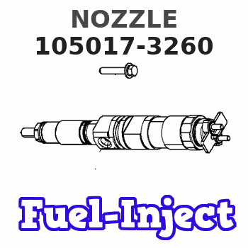
Information nozzle
BOSCH
9 432 612 855
9432612855
ZEXEL
105017-3260
1050173260
ISUZU
8973293390
8973293390
Rating:
Compare Prices: .
As an associate, we earn commssions on qualifying purchases through the links below

105017-3260 DLLA136PN326 .4Pcs Fuel Injector .Compatible For ISUZU 4JH1 4HK1
SLWHHDBT 1.Compatible For ISUZU 4JH1 4HK1 || 2. Excellent fuel atomization effect: Using advanced technology, it can fine atomize fuel, make fuel and air fully mixed, improve combustion efficiency, and provide more powerful power output for the engine || 3. High-quality materials: The selection of high-quality materials carefully made, with excellent wear resistance, can work stably for a long time, extend service life, reduce the frequency of replacement || 4. Improve driving performance: Optimized injection design helps improve engine response speed and fuel economy, allowing the vehicle to accelerate more smoothly and drive more smoothly, giving you a better driving experience || 5. Strict quality inspection: Through the strict quality inspection process, to ensure that every fuel injector can achieve excellent performance and quality, so that you can rest assured
SLWHHDBT 1.Compatible For ISUZU 4JH1 4HK1 || 2. Excellent fuel atomization effect: Using advanced technology, it can fine atomize fuel, make fuel and air fully mixed, improve combustion efficiency, and provide more powerful power output for the engine || 3. High-quality materials: The selection of high-quality materials carefully made, with excellent wear resistance, can work stably for a long time, extend service life, reduce the frequency of replacement || 4. Improve driving performance: Optimized injection design helps improve engine response speed and fuel economy, allowing the vehicle to accelerate more smoothly and drive more smoothly, giving you a better driving experience || 5. Strict quality inspection: Through the strict quality inspection process, to ensure that every fuel injector can achieve excellent performance and quality, so that you can rest assured

YIQONAPEL 4 Pieces/lot Fuel Injector Diesel Nozzle DLLA136PN326 / 105017-3260/9432612855
YIQONAPEL Wide compatibility: Compatible with a variety of vehicle models and engines. || Fuel atomization enables more complete combustion, providing powerful output. || Low - noise operation: Optimize the internal structure to reduce fuel injection noise. || Utilize technology to respond to engine commands and accurately complete fuel injection. || Stable and dependable: Maintains stable functioning under various operating conditions, ensuring more stable driving.
YIQONAPEL Wide compatibility: Compatible with a variety of vehicle models and engines. || Fuel atomization enables more complete combustion, providing powerful output. || Low - noise operation: Optimize the internal structure to reduce fuel injection noise. || Utilize technology to respond to engine commands and accurately complete fuel injection. || Stable and dependable: Maintains stable functioning under various operating conditions, ensuring more stable driving.

105017-3260 Fuel Injection Nozzle 8Pcs
DFGUFG [Product compatibility]: The OE number of this product is 105017-3260 || [Enhanced Fuel Efficiency & Power Output: Precision-engineered fuel injectors optimize spray patterns for improved combustion efficiency, directly boosting mileage while maintaining stable engine performance across all RPM ranges || [Easy to install and affordable]: Each fuel injector meets factory standard specifications, is simple and convenient to install, has higher combustion efficiency, and can effectively reduce fuel consumption || [High-quality materials for better performance]: The injectors are made of high-quality materials and advanced manufacturing processes to ensure durability and service life, allowing your engine to run smoothly for a long time || [Guaranteed Engine Performance]: This product is one of the key components of electronic fuel injection engines, helping to improve engine performance
DFGUFG [Product compatibility]: The OE number of this product is 105017-3260 || [Enhanced Fuel Efficiency & Power Output: Precision-engineered fuel injectors optimize spray patterns for improved combustion efficiency, directly boosting mileage while maintaining stable engine performance across all RPM ranges || [Easy to install and affordable]: Each fuel injector meets factory standard specifications, is simple and convenient to install, has higher combustion efficiency, and can effectively reduce fuel consumption || [High-quality materials for better performance]: The injectors are made of high-quality materials and advanced manufacturing processes to ensure durability and service life, allowing your engine to run smoothly for a long time || [Guaranteed Engine Performance]: This product is one of the key components of electronic fuel injection engines, helping to improve engine performance
You can express buy:
USD 41.91
14-06-2025
14-06-2025
4Pcs Fuel Injector Nozzle 105017-3260 NP-DLLA136PN326 for ISUZU 4JH1 4HK1
USD 53.23
14-06-2025
14-06-2025
For ISUZU 4JH1 4HK1 6Pcs Fuel Injector Nozzle Tip 105017-3260 DLLA136PN326
USD 4.5
13-05-2025
13-05-2025
Diesel Injection Nozzle DLLA136PN326 / 105017-3260 / 9432612855
Images:
USD 4.5

[13-May-2025]
USD 3.78

[28-Apr-2025]
USD 8.5

[29-Jan-2019]
Cross reference number
Zexel num
Bosch num
Firm num
Name
Information:
Additional Parts Needed for Installation
Fluid Property Sensor Mounting Bracket
A mounting bracket must be fabricated to support the Fluid Property Sensor. Since the kit can be used on a large range of engines in both stationary and machine applications, no universal mounting bracket design is possible. A bracket must be field fabricated to allow mounting of the sensor to a structural component of the machine. Leave room for electrical connection and room at each end for Engine Lubricating Oil line connections.Fittings and Adapters
Due to the large range of engines that this system may be used on, a list of all Engine Lubrication Oil line fittings, sizes, styles, and adapters are not possible. As a starting point, the inlet and outlet of the sensor adapter is a 37 degree Flare for 1" oil lines. This must be adapted to the correct size oil line tubing required for each engine. It is likely that the supply and return fuel lines will be of different sizes. It is recommended that the oil line tubing be new and in good condition. The tubing MUST be clean inside. Any small particles that are carried from the inlet hose through the transducer from the system and dislodge the particles. If hoses are equipped with O-ring fittings, the O-rings must be new.Wiring Diagram
Note: During Installation, it is important to protect wiring in key locations. Key locations are any area where the wiring could be nicked or cut and come in contact with the chassis. Avoid installation practices where there could be excessive flexing, chafing, or cutting of the wiring.
Illustration 1 g06137996
Fluid Property Sensor Wiring Schematic
Installation
Machine Preparation
Move the machine to a smooth, level location, and away from other working machines and personnel.
Lower the implements to the ground.
Stop the engine.
Engage the parking brake for the machine.
Place the disconnect switch in the OFF position.
Follow all LOTO instructions for the machine.Installation of the Fluid Property Sensor
The Fluid Property Sensor must be located on a field fabricated bracket in a location of the installer's choice. When selecting a mounting location, the installer must mount the sensor in an area off the engine to reduce vibration of the sensor as well as accessibility of sensor and electrical connection. Electrical connections should avoid sharp bends at connectors, sharp edges, and chafing surfaces. Harnesses should be supported at no less than 30.48 cm (12 inch) intervals. The Fluid Property Sensor must be installed with the orifice opening in the upright position as shown in Illustration 2.
Illustration 2 g06138010
Fluid Property Sensor Installation
(A) Oil Pump
(B) Oil Filter
(C) Engine Oil Gallery
(D) Isolation Valve
(E) Oil Flow
(F) Fluid Property Sensor Orientation
(G) Oil Reservoir
(H) Oil Strainer
(I) Engine Oil SumpInstallation of the Electrical Harnesses
Note: During installation, it is important to protect wiring in key locations. Key locations are any area where the wiring could be nicked or cut and come in contact with the chassis. Avoid installation practices where there could be excessive flexing, chafing, or cutting of the wiring.
Install the 514-3811 Instl GP-Field (Fluid Property Harness) on Fluid Property Sensor.
Route harness back