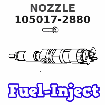
Information nozzle
BOSCH
9 432 610 882
9432610882
ZEXEL
105017-2880
1050172880
ISUZU
8972413620
8972413620
Rating:
Compare Prices: .
As an associate, we earn commssions on qualifying purchases through the links below

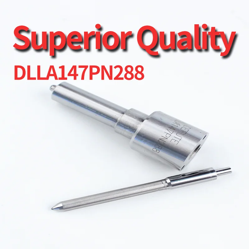
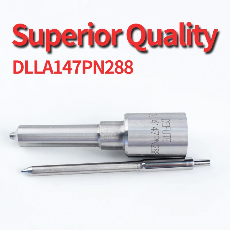
FYFMG 1Pcs DLLA147PN288 105017-2880 PNseries Diesel Engine Injection Nozzle Diesel Engine Accessories Oil Head Couple 1050172880
FYFMG Precise matching: designed Compatible for diesel engine injection nozzle and other diesel engines to ensure good compatibility with the vehicle system and improve operational efficiency || Compliance for OEM standards: Developed based on OEM No. DLLA147PN288, it meets the requirements of the original specifications with stable and reliable performance || Optimize fuel efficiency: Improve the fuel atomization effect, help the engine burn more fully, reduce fuel consumption || Enhance driving experience: Ensure accurate fuel injection, making the engine run more smoothly and the power response more quickly || Economical and practical: outstanding cost performance, suitable for replacing old or damaged injectors, helping to save maintenance costs
FYFMG Precise matching: designed Compatible for diesel engine injection nozzle and other diesel engines to ensure good compatibility with the vehicle system and improve operational efficiency || Compliance for OEM standards: Developed based on OEM No. DLLA147PN288, it meets the requirements of the original specifications with stable and reliable performance || Optimize fuel efficiency: Improve the fuel atomization effect, help the engine burn more fully, reduce fuel consumption || Enhance driving experience: Ensure accurate fuel injection, making the engine run more smoothly and the power response more quickly || Economical and practical: outstanding cost performance, suitable for replacing old or damaged injectors, helping to save maintenance costs

12 Pcs Diesel Fuel PN Injection Nozzle DLLA147PN288 105017-2880 For Replacement
XDEP Stamping No.: DLLA147PN288 || Nozzle NO.: 105017-2880 || Application: Diesel Fuel Injection Nozzle Replacement || Guarantee: 6 Months Warranty,100% Tested Before Shipping to Ensure Product Safety,Stability and Durability || Advantage: High-Quality Material for Long-Lasting Durability. Perfect Match for the Injector and Easy to Install
XDEP Stamping No.: DLLA147PN288 || Nozzle NO.: 105017-2880 || Application: Diesel Fuel Injection Nozzle Replacement || Guarantee: 6 Months Warranty,100% Tested Before Shipping to Ensure Product Safety,Stability and Durability || Advantage: High-Quality Material for Long-Lasting Durability. Perfect Match for the Injector and Easy to Install

$13.53
02 Jan 2025
VN: Laminee
DIESEL FUEL INJECTOR DLLA154PN161 DLLA157PN201 DLLA147PN288 DLLA141PN136 DLLA160PN129 DLLA160PN100 DLLA154PN067 - (Color: DLLA141PN136)
Generic Color: DLLA141PN136
Generic Color: DLLA141PN136
You can express buy:
USD 3.58
13-05-2025
13-05-2025
DLLA147PN288 PN series diesel engine injection nozzle 105017-2880 Diesel engine accessories oil head couple 1050172880
USD 13.72
13-05-2025
13-05-2025
4 Piece-set DLLA147PN288 105017-2880 PNseries diesel engine injection nozzle Diesel engine accessories oil head couple1050172880
Include in #1:
101402-7660
as NOZZLE
Cross reference number
Zexel num
Bosch num
Firm num
Name
Information:
Safety Section
Care must be taken to ensure that fluids are contained during performance of inspection, maintenance, testing, adjusting, and repair of the product. Be prepared to collect the fluid with suitable containers before opening any compartment or disassembling any component containing fluids.Refer to Special Publication, NENG2500, "Dealer Service Tool Catalog" for tools and supplies suitable to collect and contain fluids on Cat® products.Dispose of all fluids according to local regulations and mandates.
Illustration 1 g00104545Prevent the machine from movement. Park the machine on a level surface.Attach a "Do Not Operate" warning tag or a similar warning tag to the start switch or to the controls before you service the equipment. These warning tags (Special Instruction, SEHS7332) are available from your Caterpillar dealer.Required Parts
Table 1 contains the parts needed to complete the installation of the new DEF filter.Note: Only one DEF filter group is required per engine. Use Table 2 to determine which filter is the appropriate filter for each DEF header. Illustration 2 shows the location of the DEF header part number.
Table 1
Part Number Part Description Qty
378-3187 Diesel Exhaust Fluid Filter Gp 1
423-3251 Connector 1
391-5262 Gasket 1
425-0385 Filter As 1
452-6055 Filter Base As 1
453-1604(1) Diesel Exhaust Fluid Filter Gp 1
453-1605(1) Diesel Exhaust Fluid Filter Gp 1
453-1606(1) Diesel Exhaust Fluid Filter Gp 1
(1) Use Table 2 to choose the correct part that corresponds to the DEF header
Illustration 2 g03745839
(1) Location of DEF heater part number
Table 2
DEF Heater Part Number Required DEF Filter
434-3241 453-1604
434-3242 453-1605
434-3243 453-1606 Installation Procedure
Ensure that the area around the DEF heater is clean and free from debris.
Remove manifold DEF heater from DEF tank. Refer to Disassembly and Assembly, Manifold (DEF Heater) - Remove and Install for the correct procedure.
Illustration 3 g06013988
Typical example
Position filter base assembly (3) to DEF heater (2). Install screws (1) to filter base assembly (3). Tighten the self-tapping screws (1) securely.Note: Each half of the adapter has two small locking tabs that secure to the bottom side of the DEF heater.
Remove existing filter from the pickup pipe on manifold DEF heater. Refer to Disassembly and Assembly, Manifold (DEF Heater) - Remove and Install for the correct procedure.
Install a new filter to the pickup pipe on manifold DEF heater. Refer to Disassembly and Assembly, Manifold (DEF Heater) - Remove and Install for the correct procedure.
Illustration 4 g06013992
Typical example
Position the correct DEF filter (5) to the filter base assembly (3). Install band clamp (4). Tighten the band clamp to a torque