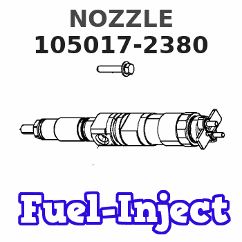
Information nozzle
BOSCH
9 432 610 461
9432610461
ZEXEL
105017-2380
1050172380
ISUZU
8972034701
8972034701
Rating:
Compare Prices: .
As an associate, we earn commssions on qualifying purchases through the links below

FYFMG 1Pcs DSLA150P1019 DSLA150P520 DSLA145P882 DLLA145PN238 DSLA145P366 DSLA150P706 DSLA150P280 DSLA150P672 Diesel Fuel Injector Nozzle(DSLA150P280)
FYFMG Precise matching: designed Compatible for Diesel Fuel Injector Nozzle and other diesel engines to ensure good compatibility with the vehicle system and improve operational efficiency || Compliance for OEM standards: Developed based on OEM No. DSLA150P1019, it meets the requirements of the original specifications with stable and reliable performance || Optimize fuel efficiency: Improve the fuel atomization effect, help the engine burn more fully, reduce fuel consumption || Enhance driving experience: Ensure accurate fuel injection, making the engine run more smoothly and the power response more quickly || Economical and practical: outstanding cost performance, suitable for replacing old or damaged injectors, helping to save maintenance costs
FYFMG Precise matching: designed Compatible for Diesel Fuel Injector Nozzle and other diesel engines to ensure good compatibility with the vehicle system and improve operational efficiency || Compliance for OEM standards: Developed based on OEM No. DSLA150P1019, it meets the requirements of the original specifications with stable and reliable performance || Optimize fuel efficiency: Improve the fuel atomization effect, help the engine burn more fully, reduce fuel consumption || Enhance driving experience: Ensure accurate fuel injection, making the engine run more smoothly and the power response more quickly || Economical and practical: outstanding cost performance, suitable for replacing old or damaged injectors, helping to save maintenance costs

DLLA143PN265 .DLLA140PN359 .DLLA144PN309 .DLLA145PN382 DLLA152PN381 PN248 Diesel Fuel Injector Nozzle DLLA145PN238 105017-2380 - (Color: DLLA144PN309)
Generic Color: DLLA144PN309
Generic Color: DLLA144PN309
You can express buy:
USD 19.26
14-06-2025
14-06-2025
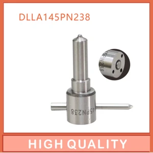
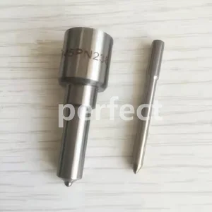
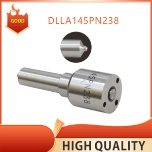
4 Pieces DLLA145PN238 diesel fuel injection nozzle DLLA145PN238 105017-2380 for Isuzu 4JB1 6DL1 280hp fuel injection nozzle
USD 57.88
14-06-2025
14-06-2025
For ISUZU Trooper NKR NHR Holden Jackaroo 4JB1TC 6x Injector Nozzle DLLA145PN238 9 432 612 582 105017-2380
USD 4.99
13-05-2025
13-05-2025
DLLA145PN238 diesel engine injection nozzle DLLA145PN238 105017-2380 is suitable for Isuzu 4JB1 6DL1 280 HP
Images:
USD 4.8

[13-May-2025]
USD 19

[13-May-2025]
USD 21.16

[28-Apr-2025]
USD 5.1

[15-Nov-2018]
Cross reference number
Zexel num
Bosch num
Firm num
Name
Information:
Introduction
This Special Instruction covers the removal procedure for DEF connectors on the models and applications listed above.Safety Section
Care must be taken to ensure that fluids are contained during performance of inspection, maintenance, testing, adjusting, and repair of the product. Be prepared to collect the fluid with suitable containers before opening any compartment or disassembling any component containing fluids.Refer to Special Publication, PERJ1017, "Dealer Service Tool Catalog" for tools and supplies suitable to collect and contain fluids on Cat® products.Dispose of all fluids according to local regulations and mandates.
Personal injury or death can result from improperly checking for a leak.Always use a board or cardboard when checking for a leak. Escaping air or fluid under pressure, even a pin-hole size leak, can penetrate body tissue causing serious injury, and possible death.If fluid is injected into your skin, it must be treated immediately by a doctor familiar with this type of injury.
Illustration 1 g00104545Prevent the machine from movement. Park the machine on a level surface.Attach a "Do Not Operate" warning tag or a similar warning tag to the start switch or to the controls before you service the equipment. These warning tags (Special Instruction, SEHS7332) are available from your Caterpillar dealer.Removal Procedure for Single Clip Connectors
Illustration 2 g03468077
(1) Line
(2) Retaining Clip
Clean the area around the connector with compressed air. Be sure to remove any dirt or debris before continuing with this procedure.
Press down on the line (1).
Press IN on the retaining clip (2).
Gently pull straight up on the line.Note: Do not pull out the clip, damage will occur to the retaining clip.Note: Do not pull off the line without the clip being fully depressed, damage will occur to the retaining clip.Removal Procedure for Dual Clip Connectors
Illustration 3 g03468506
(1) Line
(2) Retaining Clips
Clean the area around the connector with compressed air. Be sure to remove any dirt or debris before continuing with this procedure.
Press down on the line (1).
Press IN on the retaining clips (2).
Gently pull straight up on the line.Note: Do not pull out the clip, damage will occur to the retaining clip.Note: Do not pull off the line without the clip being fully depressed, damage will occur to the retaining clip.