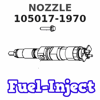
Information nozzle
BOSCH
9 432 611 016
9432611016
ZEXEL
105017-1970
1050171970
MAZDA
TF7013H55
tf7013h55
Rating:
Compare Prices: .
As an associate, we earn commssions on qualifying purchases through the links below

$63.00
14 Mar 2023
CN: lutong part plant
Diesel Fuel Injector Tips Nozzle DLLA149PN197 Injectors Nozzles 105017-1970 Car Accessories Engine Parts 6pcs Fits for MAZDA TF
DICSCL PARCS Diesel injector nozzle fits for MAZDA TF Engine || Manufacturer Part Number: DLLA149PN197 OEM Number: DLLA149PN197 || Estimated delivery time: Expedited 4-6 working days. Standard Express 7-10 working days. || If you don't know which model to choose, Please contact us. || Material: Made of high quality for longer durability and strength.100% quality inspection. Upgraded packaging avoid damage.
DICSCL PARCS Diesel injector nozzle fits for MAZDA TF Engine || Manufacturer Part Number: DLLA149PN197 OEM Number: DLLA149PN197 || Estimated delivery time: Expedited 4-6 working days. Standard Express 7-10 working days. || If you don't know which model to choose, Please contact us. || Material: Made of high quality for longer durability and strength.100% quality inspection. Upgraded packaging avoid damage.

$47.00
25 Apr 2023
CN: lutong part plant
Diesel Fuel Injector Tips Nozzle DLLA149PN197 Injectors Nozzles 105017-1970 Car Accessories Engine Parts 4pcs Fits for MAZDA TF
DICSCL PARCS Diesel injector nozzle fits for MAZDA TF Engine || Manufacturer Part Number: DLLA149PN197 OEM Number: DLLA149PN197 || Estimated delivery time: Expedited 4-6 working days. Standard Express 7-10 working days. || If you don't know which model to choose, Please contact us. || Material: Made of high quality for longer durability and strength.100% quality inspection. Upgraded packaging avoid damage.
DICSCL PARCS Diesel injector nozzle fits for MAZDA TF Engine || Manufacturer Part Number: DLLA149PN197 OEM Number: DLLA149PN197 || Estimated delivery time: Expedited 4-6 working days. Standard Express 7-10 working days. || If you don't know which model to choose, Please contact us. || Material: Made of high quality for longer durability and strength.100% quality inspection. Upgraded packaging avoid damage.

£54.19
18 Jun 2018
4.85[1.80] pounds
Bosch: Bosch
Bosch 9432611016 Hole-Type Nozzle
A brand-new Bosch OEM part || 9432611016
A brand-new Bosch OEM part || 9432611016
You can express buy:
USD 53.47
14-06-2025
14-06-2025
For Mazda Titan / Engine TF Fuel Injector Nozzle 105017-1970 DLLA149PN197
USD 41.63
19-05-2025
19-05-2025
4Pcs Fuel Injector Nozzle 105017-1970 DLLA149PN197 for Mazda Titan Engine TF
Include in #1:
101401-9442
as NOZZLE
Cross reference number
Zexel num
Bosch num
Firm num
Name
Information:
Tooling and Equipment
The tools shown in Chart F, Tooling for Finding Top Center (TC) Position, are required to complete the procedure.
Table 8
Chart F
Tooling For Finding Top Center (TC) Position
Part No Description Qty Item (1)
8T-4177 Bolt, Spring Compressor 1 7
( 1 ) Refer to the nomenclature chart at the beginning of this manual for item identification.Procedure
Illustration 39 g03425683
Timing Bolt Location (35) 8T-4177 Timing Bolt (36) Timing Hole (37) Flywheel HousingNote: Depending on engine application, timing hole (36) is located at either the left front face or the right front face of the flywheel housing.
Remove plug from the timing hole (36) on the front of the flywheel housing.
Rotate the engine with four large bolts on the front of the crankshaft. Do not use the eight small bolts on the front of the crankshaft pulley as this could cause damage to the engine.
Put 8T-4177 Bolt (35) in hole. Turn the engine flywheel counterclockwise until the timing bolt engages with the threaded hole in the flywheel.Note: If the flywheel is turned beyond the point the timing bolt engages in the threaded hole, the flywheel must be turned back at least 30 degrees clockwise. Again, turn the flywheel counterclockwise until the timing bolt engages with the threaded hole. This procedure makes sure that the play is removed from the gears when number 1 piston is put on TC.
Remove the cylinder head valve cover.
Illustration 40 g03425694
Valve Cover Removed
The intake and the exhaust valves for the number 1 cylinder are fully closed if number 1 piston is on the compression stroke and the rocker arms can be moved by hand. If the rocker arms cannot be moved and the valves are slightly open, the number 1 piston is on the exhaust strike. Refer to Chart E, Crankshaft Positions for Fuel Timing Settings, to determine which cylinders can be checked/adjusted (determined by stroke position of crankshaft when timing bolt is installed).Note: When the actual stroke position is identified, and the other stroke position is desired, it is necessary to remove the timing bolt from the flywheel. Turn the flywheel counterclockwise 360 degrees, and reinstall the timing bolt.
After TC position for a particular stroke is obtained and adjustments are made, remove the timing bolt and turn the flywheel counterclockwise 360 degrees. This will put number 1 piston at TC position on the other stroke. Install timing bolt in the flywheel and complete adjustments for remaining cylinders.Removal and Installation of Unit Fuel Injectors
Table 9
Chart G
Injector Removal and Installation Tools
Part No Description Qty Item (1)
5P-0302 Injector Removal Bar 1 16
194-3542 Hex Socket Bit Driver, 5 mm 1 18
( 1 ) Refer to nomenclature chart, at the beginning of this manual for item identification.
Illustration 41 g03425701
Unit Fuel Injector (48) Bolt (49) O-RingsNote: Not all injectors use a bottom O-ring.Removal
Remove injector hold down bolt (48) .
Do not pry on the injector hold down bracket.