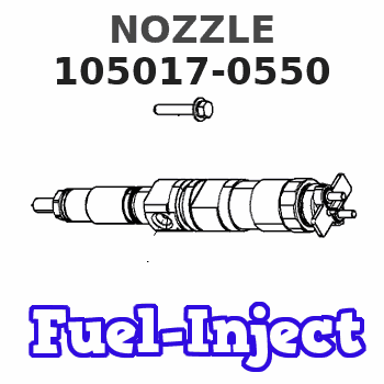
Information nozzle
BOSCH
9 432 610 253
9432610253
ZEXEL
105017-0550
1050170550
ISUZU
8944500511
8944500511
Rating:
Compare Prices: .
As an associate, we earn commssions on qualifying purchases through the links below

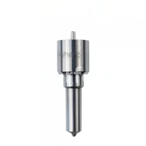
12 Pcs Diesel Fuel PN Injection Nozzle DLLA146PN055 105017-0550 For Replacement
XDEP Stamping No.: DLLA146PN055 || Nozzle NO.: 105017-0550 || Application: Diesel Fuel Injection Nozzle Replacement || Guarantee: 6 Months Warranty,100% Tested Before Shipping to Ensure Product Safety,Stability and Durability || Advantage: High-Quality Material for Long-Lasting Durability. Perfect Match for the Injector and Easy to Install
XDEP Stamping No.: DLLA146PN055 || Nozzle NO.: 105017-0550 || Application: Diesel Fuel Injection Nozzle Replacement || Guarantee: 6 Months Warranty,100% Tested Before Shipping to Ensure Product Safety,Stability and Durability || Advantage: High-Quality Material for Long-Lasting Durability. Perfect Match for the Injector and Easy to Install

105017-0550 Fuel Injection Nozzle 8Pcs
DFGUFG [Product compatibility]: The OE number of this product is 105017-0550 || [Enhanced Fuel Efficiency & Power Output: Precision-engineered fuel injectors optimize spray patterns for improved combustion efficiency, directly boosting mileage while maintaining stable engine performance across all RPM ranges || [Easy to install and affordable]: Each fuel injector meets factory standard specifications, is simple and convenient to install, has higher combustion efficiency, and can effectively reduce fuel consumption || [High-quality materials for better performance]: The injectors are made of high-quality materials and advanced manufacturing processes to ensure durability and service life, allowing your engine to run smoothly for a long time || [Guaranteed Engine Performance]: This product is one of the key components of electronic fuel injection engines, helping to improve engine performance
DFGUFG [Product compatibility]: The OE number of this product is 105017-0550 || [Enhanced Fuel Efficiency & Power Output: Precision-engineered fuel injectors optimize spray patterns for improved combustion efficiency, directly boosting mileage while maintaining stable engine performance across all RPM ranges || [Easy to install and affordable]: Each fuel injector meets factory standard specifications, is simple and convenient to install, has higher combustion efficiency, and can effectively reduce fuel consumption || [High-quality materials for better performance]: The injectors are made of high-quality materials and advanced manufacturing processes to ensure durability and service life, allowing your engine to run smoothly for a long time || [Guaranteed Engine Performance]: This product is one of the key components of electronic fuel injection engines, helping to improve engine performance

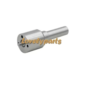
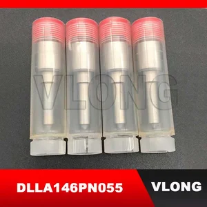
Diesel Injection Nozzle Types 4 Pack DLLA146PN055 105017-0550 Fuel Injector Nozzle Fits for Isuzu 4JB1 4JB1CT 4JB1CGT Engine
Generic Manufacturer Part Number: DLLA146PN055 , 8944500511 , 9432610253 , H105017055 , 105017-0550 , NP-DLLA146PN055 || Package: 4pieces of injector nozzles.Neutral packing || Size: Standard size,Fuel injector nozzle for diesel engine || Material: Made of high speed steel material,anti-rust, not easy to clog for long time use || Compatible with Fuel Injector: 105118-4401 , 105118-4403 , 105118-4404 , 8944500501 , 8944500502
Generic Manufacturer Part Number: DLLA146PN055 , 8944500511 , 9432610253 , H105017055 , 105017-0550 , NP-DLLA146PN055 || Package: 4pieces of injector nozzles.Neutral packing || Size: Standard size,Fuel injector nozzle for diesel engine || Material: Made of high speed steel material,anti-rust, not easy to clog for long time use || Compatible with Fuel Injector: 105118-4401 , 105118-4403 , 105118-4404 , 8944500501 , 8944500502
You can express buy:
USD 54.72
14-06-2025
14-06-2025
For ISUZU 4JB1 8944500502 6Pcs Fuel Injector Nozzle Tip 105017-0550 DLLA146PN055
USD 34.92
19-05-2025
19-05-2025
4Pcs Fuel Injector Nozzle 105017-0550 for ISUZU 4JB1 8944500502
USD 26
13-05-2025
13-05-2025
4PCS Fuel Injector Sparyer PN Type Diesel Nozzle 9 432 610 253 9432610253 105017-0550 1050170550 DLLA146PN055 For ISUZU 4JB1CT
Images:
USD 26

[13-May-2025]
USD 19.9

[01-May-2025]
USD 4

[12-Nov-2023]
Include in #2:
104741-1403
as NOZZLE
Cross reference number
Zexel num
Bosch num
Firm num
Name
Information:
The Caterpillar Electronic Technician (ET)
Illustration 1 g00777826
The Caterpillar Electronic Technician (ET) is a software program that is used to access data. The service technician can use the Caterpillar Electronic Technician in order to perform maintenance work on the machine. Some of the options that are available with the Caterpillar Electronic Technician are listed below:
View Diagnostic codes. See Troubleshooting, "Using the Caterpillar Electronic Technician to Determine Diagnostic Codes".
View the status of parameters.
Clear active diagnostic codes and clear logged diagnostic codes
Perform calibration of machine systems.
Program the ECM (Flash). This is done with the "WINflash" program. See Testing and Adjusting, "Electronic Control Module (ECM) - Flash Program".
Print reports.The following list contains some of the diagnostic functions and programming functions that are performed by the service tools.
The failures of the ECM system are displayed.
The status of most of the inputs and the outputs are displayed.
The settings for the ECM are displayed.
Display the status of the input and output parameters in real time.
Display the clock hour of the internal diagnostic clock.
The number of occurrences and the clock hour of the first occurrence and the last occurrence is displayed for each logged diagnostic code.
The definition for each logged diagnostic code and each event is displayed.
Load new FLASH software.See Troubleshooting, "Diagnostic Code List" for the list of diagnostic codes for the ECM.See Troubleshooting, "Using the Caterpillar Electronic Technician to Determine Diagnostic Codes". Diagnostic information is accessed with the following drop down menus:
Active diagnostic codes
Logged diagnostic codesSensor Diagnostics
The following tables show the conditions that the diagnostic codes are set for each sensor. If any of the diagnostic codes are active, the System Problem for the LED will be turned on. During the Debounce time, the affected parameter will remain at the last good value. After the Debounce time, the affected parameter will be set to the default value. Refer to Table 1.
Table 1
Sensor Sample Period (mS) Too Low Too High Defaults
Inlet Pressure (gauge) Code Condition Debounce Code Condition Debounce NA
1 81-4 Input < 0.5 VDC 5 sec on
5 sec off 81-3 Input greater than 4.5 VDC 5 sec on
5 sec off NA
Exhaust Temperature 1 535-4 Input < 1.5 VDC 5 sec on
5 sec off 535-3 Input greater than 4.0 VDC 5 sec on
5 sec off NA Temperature Sensor
Table 2 refers to the properties of the temperature sensor.
Table 2
Function Part Number Measure Range Output Accuracy Power Supply Sensor Mounting Mating
Exhaust Temperature 280-3921
50 °C (122 °F)to
850 °C (1562 °F) N/A
500° 5°C (932° 9°F) to
850° 5°C (1562° 9°F) 5V (+/- 0.5) Thread Size: M14 X 1.5
Probe Length:
70 mm (2.7559 inch) from flange to tip 230-5008 Connector Plug As Pressure Sensor
Table 3
Function PN Max Pressure Measure Burst Pressure Power