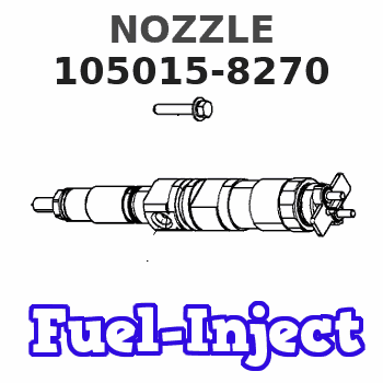
Information nozzle
BOSCH
9 432 610 510
9432610510
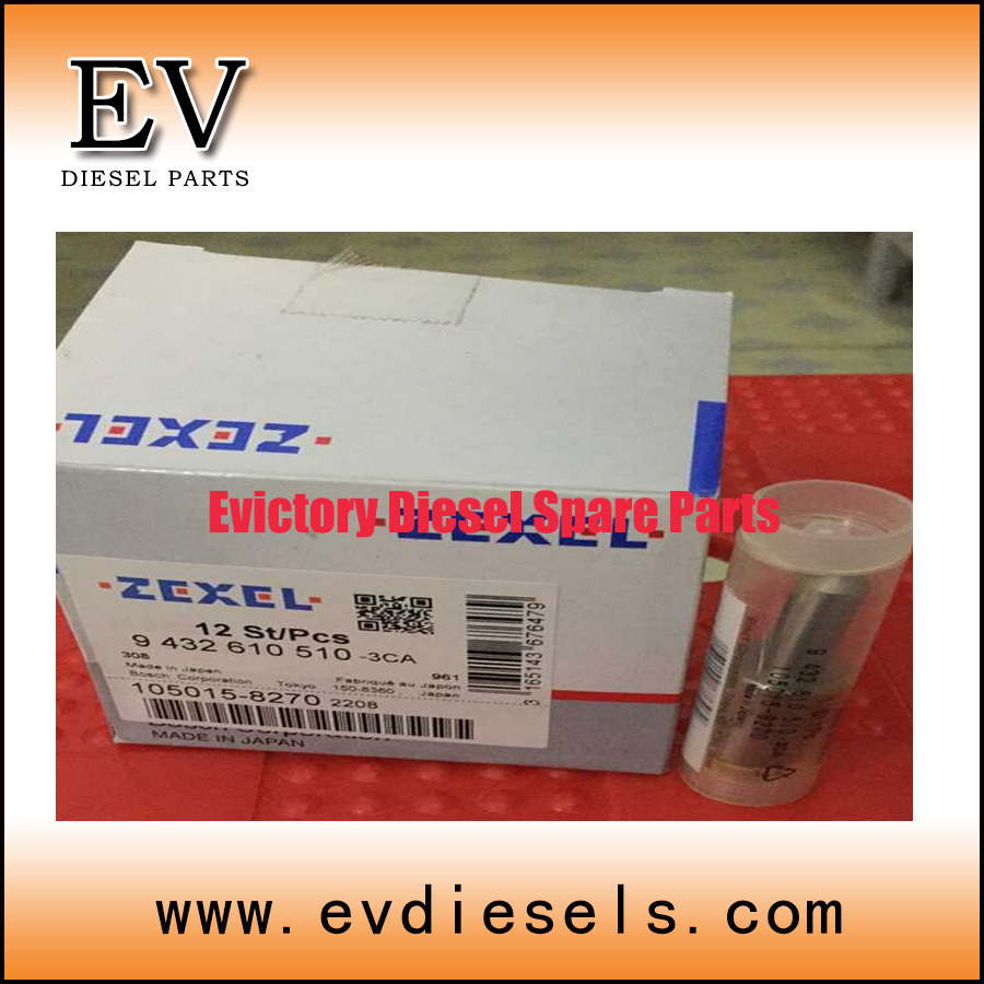
ZEXEL
105015-8270
1050158270
MITSUBISHI
ME726490
me726490
Rating:
Compare Prices: .
As an associate, we earn commssions on qualifying purchases through the links below

YANNAL PART Fuel Injector Nozzle Suitable for Mitsubishi 8DC8 Engine Part 105015-8270
YANNAL PART Product Name: Fuel Injector Nozzle || Part Number: 105015-8270 || Application: Compatible for Mitsubishi 8DC8 || Warranty: 1 Year || Note: Please verify your part number before ordering, any problem please feel free to contact us, thanks.
YANNAL PART Product Name: Fuel Injector Nozzle || Part Number: 105015-8270 || Application: Compatible for Mitsubishi 8DC8 || Warranty: 1 Year || Note: Please verify your part number before ordering, any problem please feel free to contact us, thanks.
YANNAL PART 8DC9 Fuel Injector Nozzle 105015-8270 Suitable for Mitsubishi Engine Part
YANNAL PART Product Name: Fuel Injector Nozzle || Part Number: 105015-8270 || Application: Compatible for Mitsubishi 8DC9 || Warranty: 1 Year || Note: Please verify your part number before ordering, any problem please feel free to contact us, thanks.
YANNAL PART Product Name: Fuel Injector Nozzle || Part Number: 105015-8270 || Application: Compatible for Mitsubishi 8DC9 || Warranty: 1 Year || Note: Please verify your part number before ordering, any problem please feel free to contact us, thanks.
YANNAL PART 105015-8270 Fuel Injector Nozzle Suitable for Mitsubishi Engine Part 8DC10
YANNAL PART Product Name: Fuel Injector Nozzle || Part Number: 105015-8270 || Application: Compatible for Mitsubishi 8DC10 || Warranty: 1 Year || Note: Please verify your part number before ordering, any problem please feel free to contact us, thanks.
YANNAL PART Product Name: Fuel Injector Nozzle || Part Number: 105015-8270 || Application: Compatible for Mitsubishi 8DC10 || Warranty: 1 Year || Note: Please verify your part number before ordering, any problem please feel free to contact us, thanks.
You can express buy:
USD 4.42
28-06-2019
28-06-2019
105015-8270 Assembly Injector Diesel Nozzle Precision Accessories
USD 4.42
28-06-2019
28-06-2019
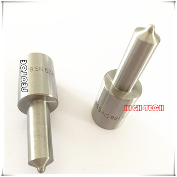
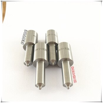
Diesel Spare Parts Nozzle DLLA160SN827 High Quality 105015-8270
USD 300
21-06-2017
21-06-2017
Japan 105015-8270 injector nozzle DLLA160SN827 FOR 8DC8 8DC9 8DC10 8DC11 engine
Images:
USD 41.99

[14-Jun-2018]
USD 60

[09-Feb-2017]
Cross reference number
Zexel num
Bosch num
Firm num
Name
Information:
1. Remove wiring harnesses from bracket (1). 2. Disconnect the wires at connections (5). Remove seal wire (4). Remove five bolts (2), bracket (1) cover (3) and the gasket. 3. Remove two bolts (6) and clamps. Remove rack solenoid (7). 4. Disconnect wires at connections (8). Remove two bolts (10) and bracket assembly (9). Loosen the locknut and remove rack position sensor (11). Be careful not to lose the spring that is around the sensor. To remove the transducer module at this time use the following procedure:a. disconnect wires at connector (8).b. remove the connectors from the wires.c. remove four bolts that fasten transducer module (22) to housing (18).d. feed the wires through housing (18) while removing the transducer module. 5. Remove three bolts (12) from inside housing (14). Remove two bolts (13) and remove housing (14).
Typical Example6. Loosen locknut (15) and remove engine speed sensor (16).
Typical Example7. Remove seven bolts (17) and remove the transducer module and housing (18). 8. Remove three bolts (19) and cover (20). 9. Remove two bolts (21). Remove transducer module (22) and gasket. 10. Remove lockring (27), seat (25), spring (24), sleeve (23) and lockring (26). 11. Remove three bolts (28) and remove cylinder (29). 12. Remove sleeve (30), piston (31) and valve (32). Remove O-ring seal (33) from sleeve (30). 13. Remove bolts (34) and remove retainer (35). Remove two races and one bearing (not shown). Assemble Rack Actuator Package
1. Lubricate bearing (37) with engine oil. Install race (36), bearing (37), race (36) and retainer (35) on the fuel injection pump camshaft. 2. Lubricate O-ring seal (33) with engine oil and install on sleeve (30). Install valve (32) and piston (31) into sleeve (33). 3. Install sleeve (30) into cylinder (29).4. Install lockring (26), sleeve (23), spring (24), seat (25) and lockring (27) on valve (32). 5. Put cylinder assembly (29) in position on the fuel injection pump housing with piston (31) engaged over fuel injection pump rack (38). Be sure that rack (38) is properly engaged with piston (31). 6. Fasten cylinder (29) to the fuel injection pump housing with three bolts (28). The rack and servo valve (32) must move freely after bolts (28) are tight. 7. Install gasket (39) and transducer module (22) on housing (18). 8. Place wire harness (40) in the slot of the housing. 9. Install cover (20) and bolts (19).
Typical Example10. Install the gasket and housing (18) on the fuel injection pump housing with seven bolts (17).
Typical Example11. Install engine speed sensor (16) until it contacts retainer (35). Back the engine speed sensor out (counterclockwise) 180°. This procedure will provide a clearance of .76 mm (.030 in). Tighten locknut (15).
Typical Example12. Install gasket and housing (14).13. Install the rack position sensor damping seal in housing (14). Install the spring and rack position sensor (11) in housing (14).14. Connect the rack position sensor wiring connector to the transducer module wiring connector (P1 to J1). Connect the transducer module wiring connector to the control module wiring