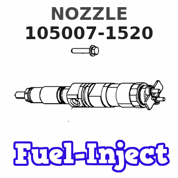
Information nozzle
BOSCH
9 432 610 436
9432610436
ZEXEL
105007-1520
1050071520
Rating:
Compare Prices: .
As an associate, we earn commssions on qualifying purchases through the links below

FYFMG 1Pcs DN0PDN112 DN0PDN121 DN0PDN124 DN20PD32 DN0PD95 Diesel Engine Fuel Injection Nozzle NP-DNOPDN121 105007-1210(DN0PDN121)
FYFMG Precise matching: designed Compatible for FUEL INJECTION NOZZLE and other diesel engines to ensure good compatibility with the vehicle system and improve operational efficiency || Compliance for OEM standards: Developed based on OEM No. DN0PDN112, it meets the requirements of the original specifications with stable and reliable performance || Optimize fuel efficiency: Improve the fuel atomization effect, help the engine burn more fully, reduce fuel consumption || Enhance driving experience: Ensure accurate fuel injection, making the engine run more smoothly and the power response more quickly || Economical and practical: outstanding cost performance, suitable for replacing old or damaged injectors, helping to save maintenance costs
FYFMG Precise matching: designed Compatible for FUEL INJECTION NOZZLE and other diesel engines to ensure good compatibility with the vehicle system and improve operational efficiency || Compliance for OEM standards: Developed based on OEM No. DN0PDN112, it meets the requirements of the original specifications with stable and reliable performance || Optimize fuel efficiency: Improve the fuel atomization effect, help the engine burn more fully, reduce fuel consumption || Enhance driving experience: Ensure accurate fuel injection, making the engine run more smoothly and the power response more quickly || Economical and practical: outstanding cost performance, suitable for replacing old or damaged injectors, helping to save maintenance costs

DN0PDN121 DN0PDN124 DN0PDN112 DN20PD32 DN0PD95 Diesel Engine Fuel Injection Nozzle NP-DNOPDN121 105007-1210 - (Color: DN0PD95)
Generic Color: DN0PD95
Generic Color: DN0PD95

4PCS DN20PD32 New DL Fuel Injector Nozzle for TA 1C 2C 1CL 2CL 2CT
KICDHVU Precise Fuel Delivery: DN20PD32 nozzle design ensures precise and atomized fuel delivery, optimizing combustion efficiency in your TA DL engine. || Improved Engine Performance: Enhances engine power, torque, and fuel economy by providing a consistent and efficient fuel spray pattern with these 4PCS DL Fuel Injector Nozzles.. || Direct Fit Replacement: Designed as a direct replacement for TA 1C, 2C, 1CL, 2CL, and 2CT DL engines, ensuring easy installation and compatibility. || Quality Construction: Manufactured to meet or exceed OEM specifications, using durable materials for long-lasting performance and reliability. || Complete Set of 4: Comes as a complete set of four (4) nozzles, allowing for a full injector overhaul to restore optimal engine function and prevent uneven wea
KICDHVU Precise Fuel Delivery: DN20PD32 nozzle design ensures precise and atomized fuel delivery, optimizing combustion efficiency in your TA DL engine. || Improved Engine Performance: Enhances engine power, torque, and fuel economy by providing a consistent and efficient fuel spray pattern with these 4PCS DL Fuel Injector Nozzles.. || Direct Fit Replacement: Designed as a direct replacement for TA 1C, 2C, 1CL, 2CL, and 2CT DL engines, ensuring easy installation and compatibility. || Quality Construction: Manufactured to meet or exceed OEM specifications, using durable materials for long-lasting performance and reliability. || Complete Set of 4: Comes as a complete set of four (4) nozzles, allowing for a full injector overhaul to restore optimal engine function and prevent uneven wea
You can express buy:
USD 4
13-05-2025
13-05-2025
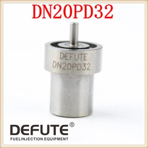
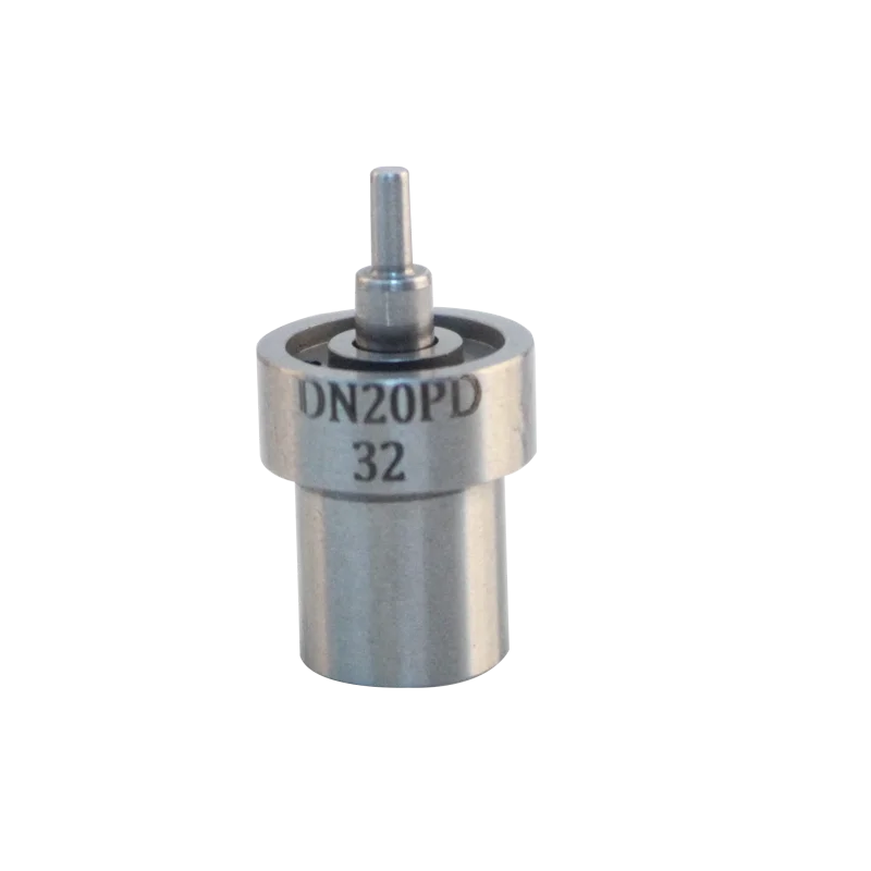
DN20PD32 nozzle /injector nozzle/Diesel nozzle 105007-1520 NP-DN20PD32 for T-OYOTA 2C/1HZ/2C-L
USD 3.98
28-04-2025
28-04-2025
High quality injector 105007-1520 093400-5320 093400-5420 Diesel injector nozzle DN20PD32

USD 4
12-11-2023
12-11-2023
brand new Excellent Quality Injector 105007-1520 093400-5320 093400-5420 Diesel Injector Nozzle DN20PD32
Images:
USD 3.5

[23-Aug-2022]
USD 16

[10-Nov-2022]
USD 20.39

[22-Feb-2019]
USD 16.5

[10-Nov-2022]
Cross reference number
Zexel num
Bosch num
Firm num
Name
Information:
Introduction
Do not perform any procedure in this Special Instruction until you have read the information and you understand the information.If the crankshaft and/or flywheel are replaced or set, it is necessary to calibrate the injection timing. The following steps show how to calculate/determine the new injection timing by measuring angular deviation between the crankshaft TDC and Crank Position sensor detected TDC.Note: Once completed the engine ecm must be reprogrammed with the new injection timing value.Follow all Steps below.Required Tools
Dial Gauge
Tri - Square
483-5054 C2.4 Injection Top Correction JigProcedure
Illustration 1 g06220154
(1) Rocker Arm
(2) Valve Spring
While the engine is out of the machine, remove the valve cover and rocker arm (1).
Illustration 2 g06220155
(3) Dial Gauge
(4) O-ring
(5) Exhaust Valve
Align the #4 piston with TDC and remove the valve spring (2) of the #4 cylinder. Insert an O-ring (4) to prevent the exhaust valve (5) from falling into the cylinder and position the dial gauge (3) at the tip of the valve.
While turning the flywheel counterclockwise, stop the flywheel when you see the largest needle movement on the gauge. Which indicates TDC.
Illustration 3 g06220158
(6) Tri - Square
Illustration 4 g06220159
(7) Mark for TDC
(8) Reference Line
While the flywheel is in this position, set the tri-square (6) as indicated in the Illustration 3 and place a TDC mark (7) on the reference line (8) and flywheel on the engine body side. In the case the flywheel is turned too far, return flywheel by turning clockwise and start over.
Illustration 5 g06220162
(9) Area where there is no pulsar hole
(10) Flywheel
(11) Flywheel Housing
(12) Crank Position Sensor Mounting Hole
(13) Reference Pulsar Hole 20th
To confirm that the crank position sensor is at the TDC detection position: Align the reference 20th pulsar hole (13) from the area where there is no pulsar hole (9) on the outer circumference of the flywheel (10) with the crank position sensor mounting hole (12) on the flywheel housing (12).
Illustration 6 g06220413
(14) Injection Top Correction Jig
Insert the injection tooling jig (14) into the crank position sensor mounting hole and align the center of the handle and pulsar.
Illustration 7 g06220442
(6) Tri - Square
(8) Reference Line
Illustration 8 g06220454
(15) Mark of Crank Position Sensor TDC Detection Position
This position is the crank position sensor TDC detection position, so position the tri - square (6) on the reference line (8) and make a crank position sensor TDC detection position mark (15) on the flywheel.
Illustration 9 g06220464
(7) Mark for TDC
(15) Mark of Crank Position Sensor TDC Detection Position
(16) Correction Amount (mm)
The difference (16) between the TDC mark (7) and the crank position sensor TDC detection mark (15) is the correction amount for fuel injection timing.To calculate the correction value: 1 mm = (360°) / (Flywheel Diameter x π)(For Example) FD = 300 mm → 1 mm = 0.38°Correction amount (CA) = 0.38 X A (mm)
If the crank position sensor top dead center detection position is in front of TDC, enter a negative value when registering injection correction value.
If the crank position sensor top dead center detection position is in back of top dead center, enter a positive value when registering injection correction