Information nameplate
BOSCH
9 461 619 656
9461619656
ZEXEL
146968-4000
1469684000
Rating:
Include in #2:
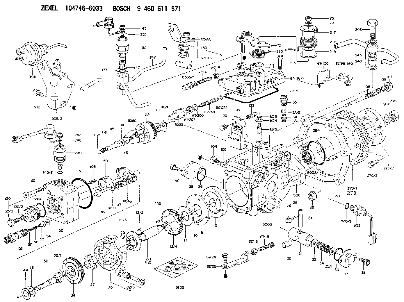
104746-6033
as NUMBER PLATE
Include in ###:
Cross reference number
Zexel num
Bosch num
Firm num
Name
146968-4000
9 461 619 656
NAMEPLATE
C 11FV NUMBER PLATE parts(VE) Others
C 11FV NUMBER PLATE parts(VE) Others
Information:
Spray starting fluid only while cranking the engine.
1. Heat the glow plugs (If equipped) for the approximate heating time shown in the STARTING AID CHART. 2. Turn the HEAT-START switch to START position. While cranking, spray starting fluid into the air inlet or air cleaner for approximately 1 second.
Wait at least 2 seconds before spraying starting fluid again.
3. If necessary, repeat the procedure.4. After the engine starts, it may be necessary to return the HEAT-START switch to the HEAT position until the engine runs smoothly.Jacket Water Heater (Attachment)
In very low temperatures, the lubricating oil must be warmed to allow starting. A jacket water heater can maintain the water temperature at approximately 90°F (32°C). The warm water will keep the oil in the upper part of the engine block warm enough to flow when starting.Dipstick Oil Heater
Contact your Caterpillar dealer before installing a dipstick crankcase oil heater.
Generator
Starting Single Unit Operation
1. Make all preliminary engine starting checks.2. Be sure the main or line circuit breaker is open.3. Start the engine and allow it to warm up.4. Close the main circuit breaker.5. Apply the load. Do not try to apply full load in one move, rather apply the load in increments to maintain system frequency at a constant level.Standby Generator Sets
Most standby units are automatic. They start, pickup the load, run and stop without an operator in attendance. Standby units can not change the governor control setting automatically. The throttle must be preset for the proper operation of that unit. Whenever the set is exercised or operated manually, be sure the throttle setting is correct for automatic operation. Check all switches to see they are properly set: Start Selector Switch in AUTOMATIC position and any Emergency Stop Switches in RUN position.Paralleling
Units may be paralleled at no load or paralleled with units under load. To parallel two or more units the following conditions must be met:1. Same phase rotation.2. Same voltage level.3. Same voltage droop.4. Same frequency.5. Voltages must be in phase.The first condition is established by "phased" wiring connections of initial installation.The second and third conditions are usually established by semi-permanent adjustments to the generator controls.The fourth and fifth conditions are under control of the operation in manual paralleling systems (or under automatic control in automatic paralleling systems).To Parallel
1. Start the unit to be paralleled.2. Turn the synchronizer lights on.3. After the engine has run long enough to warm up, bring it up to synchronous speed (the same frequency as the unit on the line). The synchronizing lights will begin to blink.4. Using the governor control, adjust the speed until the lights blink very slowly.5. The lights are off when the voltages of the two units are in phase. At this point, very quickly close the breaker while the lights are out. The frequency of the incoming unit should be slightly greater than the line frequency. This will allow the incoming unit to assume some of the load rather than add to the system load.Load Division
Once two units have been paralleled,
Have questions with 146968-4000?
Group cross 146968-4000 ZEXEL
146968-4000
9 461 619 656
NAMEPLATE