Information nameplate
BOSCH
9 461 619 803
9461619803
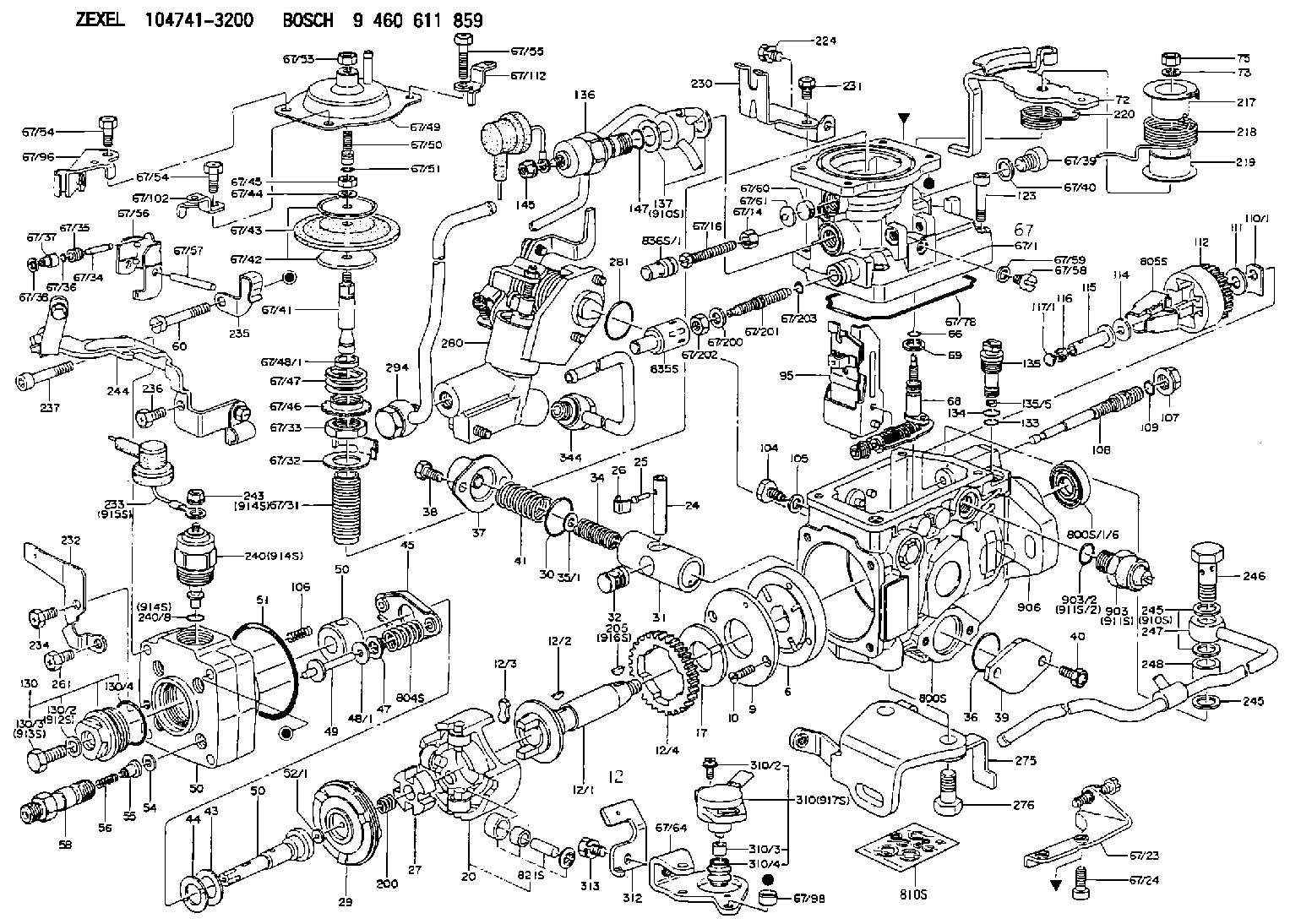
ZEXEL
146955-0000
1469550000

Rating:
Compare Prices: .
As an associate, we earn commssions on qualifying purchases through the links below

EJWFASCV PRO ECO3 480W 24V 20A Power Supply Module 1469550000 Rail Installation
EJWFASCV Wide Range Of Applications: industrial control, machinery, voltage conversion, etc || Good Performance: Long service life, can bring you convenience || Easy To Install: Small size, light weight, you can choose the switching power supply according to the model you need
EJWFASCV Wide Range Of Applications: industrial control, machinery, voltage conversion, etc || Good Performance: Long service life, can bring you convenience || Easy To Install: Small size, light weight, you can choose the switching power supply according to the model you need

NURII 3-Phase Rail Power, PRO ECO3 480W 24V 20A, 1469550000, DIN-Rail Power Supply
NURII *The power supply is made of high-quality raw materials. porous metal shell and cooling fan that makes the good heat dissipation performance. Only support indoor use || *Universal switching mode power supply. || *No noise, low temperature operation, no spontaneous combustion, no explosion, no fire hazard, stable output. || *Wide input voltage range, steady and precise output voltage.
NURII *The power supply is made of high-quality raw materials. porous metal shell and cooling fan that makes the good heat dissipation performance. Only support indoor use || *Universal switching mode power supply. || *No noise, low temperature operation, no spontaneous combustion, no explosion, no fire hazard, stable output. || *Wide input voltage range, steady and precise output voltage.

Include in #2:
104741-3200
as NUMBER PLATE
Include in ###:
Cross reference number
Zexel num
Bosch num
Firm num
Name
146955-0000
9 461 619 803
NAMEPLATE
C 11FV NUMBER PLATE parts(VE) Others
C 11FV NUMBER PLATE parts(VE) Others
Information:
Install Tooling (E). Tighten Tooling (E) to a torque of 9 1 N m (80 9 lb in).Note: The pump will not function while Tooling (E) is installed. Running the fuel injection pump with the tooling installed will result in pump damage and system contamination.
Illustration 6 g02025176
Disconnect harness assemblies (3).
Remove nut (5) and remove the clamp assembly. Discard the clamp assembly.
Loosen nuts (4) and (7). Remove the fuel line and discard the fuel line.
Disconnect hose assembly (6).
Illustration 7 g02029098
Disconnect tube assemblies (9).
Disconnect hose assemblies (10) and (11).
Remove bolts (8).
Illustration 8 g02029093
Disconnect tube assembly (12).
Illustration 9 g02025262
Remove bolts (13) and remove fuel pump (14).Installing the Fuel Injection Pump
Note: Check the O-ring seals, the gaskets, and the seals for wear or for damage. Replace the components, if necessary.
Illustration 10 g02385860
Service replacement pump
Note: Service replacement pump is shipped pinned with warning tag (Z) installed under pinch bolt (E).
Illustration 11 g02025262
Position fuel pump (14) and install bolts (13).
Illustration 12 g02029093
Connect tube assembly (12).
Illustration 13 g02029098
Install bolts (8).
Connect tube assembly (9) and connect both hose assemblies (10) and (11).
Illustration 14 g02025176Note: During installation, make sure that the fuel line caps remain in position until the fuel line is positioned near the corresponding ports in order to prevent contamination. Ensure that the areas around the rail and fuel lines are thoroughly clean before continuing this procedure. If any parts are worn or damaged, use new parts for replacement. Cleanliness is an important factor. Ensure that no debris gets introduced into the fuel system during the installation procedure. If any parts are worn or damaged, use new parts for replacement.
Connect harness assemblies (3).
Install a new fuel line. Hand tighten nuts (4) and (7).
Position the clamp assembly and install nut (5). Hand tighten the nut. Failure to place the grommet correctly on the fuel line could result in a failed fuel line.Note: Ensure that the fuel lines are centered in the nuts prior to tightening. Do not use excessive force or bending in order to assemble the fuel lines.
Tighten nut (4) at the fuel rail to a torque of 27 3 N m (239 27 lb in).
Tighten nut (7) to a torque of 27 3 N m (239 27 lb in).
Tighten nut (5) to a torque of 12 3 N m (105 27 lb in).
Illustration 15 g02351995
Remove Tooling (E) and warning tag (Z).Note: The pump will not function while Tooling (E) is installed. Running the fuel injection pump with the tooling installed will result in pump damage and system contamination.
Illustration 16 g02351981
Install O-ring seal (2) and plug (1). Tighten the plug to a torque of 9 1 N m (80 9 lb in).
Illustration 17 g02112896
Remove all tooling. Reinstall plug (X) into the timing hole that is located in the flywheel housing.
Connect Caterpillar Electronic Technician (ET). Perform a “Fuel System Functional Test ”and a “Fuel System Verification Test”.
Have questions with 146955-0000?
Group cross 146955-0000 ZEXEL
146955-0000
9 461 619 803
NAMEPLATE