Information microswitch
BOSCH
9 461 611 013
9461611013
ZEXEL
146670-2510
1466702510
MAZDA
RF0224311
rf0224311
Rating:
Include in ###:
Number on scheme 902/1

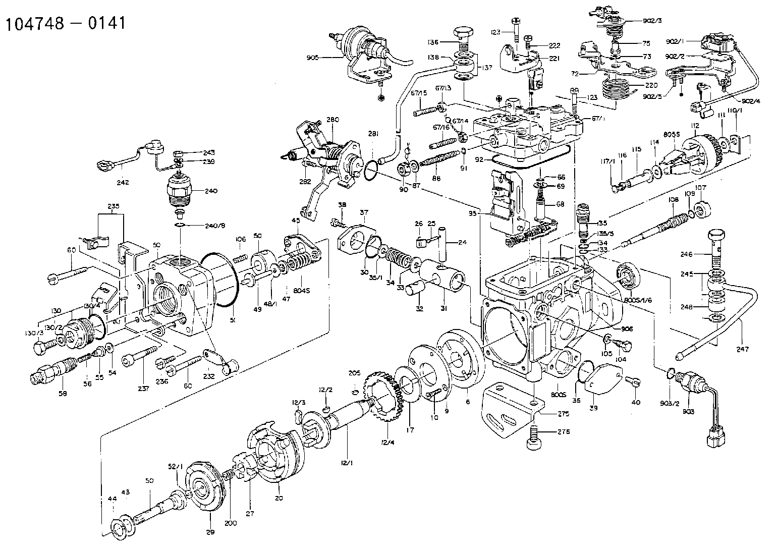
1047480141
as MICROSWITCH
1047480145
as
1047480161
as MICROSWITCH
1047480164
as
1047480168
as MICROSWITCH
1047480331
as
1047480332
as MICROSWITCH
Cross reference number
Zexel num
Bosch num
Firm num
Name
146670-2510
9 461 611 013
RF0224311 MAZDA
MICROSWITCH
A 11FV MICRO SWITCH parts(VE) Others
A 11FV MICRO SWITCH parts(VE) Others
Information:
Remove Rocker Shaft Assemblies And Push Rods
START BY:a. remove valve covers 1. Remove four bolts (1) from the turbocharger tube adapter to the aftercooler housing. Loosen the turbocharger compressor housing clamp, and rotate turbocharger tube (2) out of the way of the cylinder head assembly. 2. Remove bolts (3) that hold the valve cover bases to the cylinder head assembly. Remove valve cover bases (4).
To prevent damage to the fuel injection nozzle, hold adapter assembly (5) in position at the top of injection nozzle (6) when fuel line nut (7) is loosened or tightened.
3. Use tool (A) and a 5P328 crowfoot wrench (7/8") to loosen the fuel injection line nut at the nozzle end. 4. Use tool (B) to loosen the nut at the fuel injection line adapter end. Remove inner fuel injection lines (8). Install caps and plugs on all fuel injection line openings to keep dirt out of the fuel system. 5. Remove bolts (9) that hold the rocker shaft assemblies to the cylinder head assembly.6. Remove rocker shaft assemblies (10). 7. Put identification marks on the push rods as to their location in the engine. Remove push rods (11). 8. Put identification marks on the bridges as to their location in the engine. Remove bridges (12) from the dowels on the cylinder head assembly.Install Rocker Shaft Assemblies And Push Rods
1. Put clean engine oil on the bridges and dowels. Install the original bridges in their respective locations. New bridges can be mixed.2. Install bridges (1) on the bridge dowels. While firmly pressing 0.5 to 4.5 kg (1 to 10 lb.) straight down on the top contact surface of the bridge, turn the adjusting screw clockwise until contact is made with the valve stem. Turn the screw an additional 20° to 30° (1/3 to 1/2 of 1 hex on nut). This will straighten the dowel in the guide and compensate for the slack in the threads. Hold the adjusting screw in this position, and tighten the locknut to a torque of 30 4 N m (22 3 lb.ft.). Install original push rods in their respective locations in the engine. New push rods can be mixed.3. Install push rods (2). 4. Put rocker shaft assemblies (3) in position on the cylinder head assembly.5. Put 5P3931 Anti-Seize Compound on the threads of the bolts that hold the rocker shaft assemblies in place. Tighten the bolts first to a torque of 270 25 N m (200 18 lb.ft.). Start with the bolt in the center of the rocker shaft assembly. Tighten the bolts again to a torque of 450 20 N m (330 15 lb.ft.). Tighten the bolts again by hand to a torque of 450 20 N m (330 15 lb.ft.).
Do not cause damage to the O-ring seals on the inner fuel lines.
6. Install inner fuel injection lines (4). Tighten the fuel injection line adapter nuts (5) to a torque of 40 7 N m (30 5 lb.ft.)