Information locking washer
BOSCH
9 442 610 209
9442610209
ZEXEL
016010-0610
0160100610
ISUZU
9884102010
9884102010
Rating:
Include in ###:
Cross reference number
Zexel num
Bosch num
Firm num
Name
016010-0610
9 442 610 209
9884102010 ISUZU
LOCKING WASHER
D 90HY SNAP RING Standard parts Others
D 90HY SNAP RING Standard parts Others
016010-0610
9 442 610 209
228731100A HINO
LOCKING WASHER
D 90HY SNAP RING Standard parts Others
D 90HY SNAP RING Standard parts Others
016010-0610
9 442 610 209
228831050A HINO
LOCKING WASHER
A D 90HY SNAP RING Standard parts Others
A D 90HY SNAP RING Standard parts Others
016010-0610
9 442 610 209
ME717961 MITSUBISHI
LOCKING WASHER
D 90HY SNAP RING Standard parts Others
D 90HY SNAP RING Standard parts Others
016010-0610
9 442 610 209
1666089TA0 NISSAN
LOCKING WASHER
D 90HY SNAP RING Standard parts Others
D 90HY SNAP RING Standard parts Others
016010-0610
9 442 610 209
19322Z9002 NISSAN-DIESEL
LOCKING WASHER
D 90HY SNAP RING Standard parts Others
D 90HY SNAP RING Standard parts Others
016010-0610
9 442 610 209
030576162A MAZDA
LOCKING WASHER
D 90HY SNAP RING Standard parts Others
D 90HY SNAP RING Standard parts Others
016010-0610
9 442 610 209
SL0124316 MAZDA
LOCKING WASHER
A D 90HY SNAP RING Standard parts Others
A D 90HY SNAP RING Standard parts Others
Information:
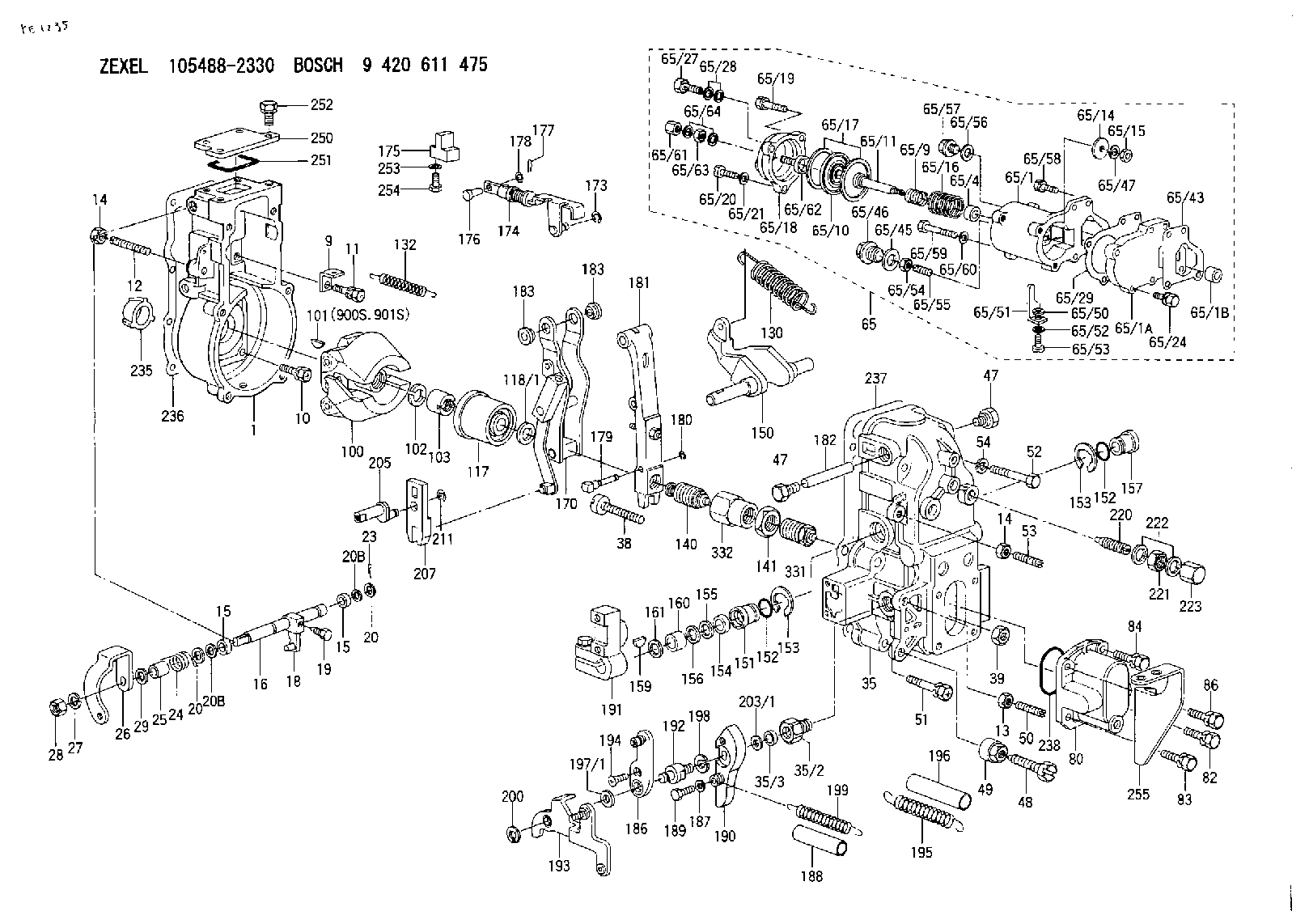
28. Remove ring (57) and dashpot assembly (58). 29. Use tool (C) to remove snap ring (64). Remove ring (63) and spool (62).30. Remove seat (61) from spring (60) and remove spring (60) from seat (59). 31. Remove spring (overfueling spring) (65) and riser (66). 32. Remove ring (67), races (68) and bearing (69). Make a replacement of shield (70) any time it is removed.33. Use a screwdriver to remove shield (70) as shown. 34. Remove bolts (71) and carrier (72). 35. Remove dowels (73) and flyweights (75).36. Remove shaft (74) and the dowel from shaft (74). 37. Remove races (76) and bearing (77).Assemble Governor
Put clean oil on all parts before assembly. Be sure all oil passages are clear. 1. Install one race (76), bearing (77) and the other race on the camshaft in the fuel injection pump housing. 2. Put flyweights (75) in position on carrier (72) and install the dowels to hold the flyweights in place. The flyweights must move freely on the dowels and have 0.010 to 0.23 mm (0.0004 to 0.009 in) end play. 3. Install dowel (78) in governor shaft (74) and install the governor shaft in the carrier as shown. 4. Put carrier (72) in position and install bolts (71). Make a replacement of shield (70) any time it is removed.5. Install shield (70) on the carrier and use tool (D) to push the shield against its seat. Use a hammer and punch to move the metal (stake) two places on the side of the shield 180° 15° apart next to the holes in the shield. 6. Install race (68), bearing (69), race (68). Use tool (C) to install the ring on riser (66) as shown. 7. Install riser (66) and spring (overfueling spring) as shown. 8. Assemble the dashpot as follows:a. Install spring (60) on seat (59) and install seat (61) in spring (60).b. Put spool and ring (63) in position on seat (61) and use tool (C) to install snap ring (64). 9. Install dashpot assembly (58) as shown. 10. Install ring (57) in the lower groove in the governor shaft. Install sleeve (56), spring (54), sleeve (56) and bearing (55). Spring (54) is used to put a preload on the thrust bearing on the camshaft in the fuel injection pump housing. 11. Use tool (B) to hold spring (54) in compression and install ring (53) in the groove in the governor shaft. Remove tool (B). 12. Put lever (52) in position on the governor servo and install pin (50) to hold the lever in place. Use a hammer and chisel to move the metal (stake) four places 90° apart on the outside surface on both legs of the governor servo to hold pin (50) in place.13. Install the O-ring seal on sleeve (49). Install piston (51) and sleeve (49) as shown.14. Install valve (44) as shown. 15. Install one lockring (48) in the groove near the center of valve (44). Put sleeve (45), spring (broken link spring) (46)
Put clean oil on all parts before assembly. Be sure all oil passages are clear. 1. Install one race (76), bearing (77) and the other race on the camshaft in the fuel injection pump housing. 2. Put flyweights (75) in position on carrier (72) and install the dowels to hold the flyweights in place. The flyweights must move freely on the dowels and have 0.010 to 0.23 mm (0.0004 to 0.009 in) end play. 3. Install dowel (78) in governor shaft (74) and install the governor shaft in the carrier as shown. 4. Put carrier (72) in position and install bolts (71). Make a replacement of shield (70) any time it is removed.5. Install shield (70) on the carrier and use tool (D) to push the shield against its seat. Use a hammer and punch to move the metal (stake) two places on the side of the shield 180° 15° apart next to the holes in the shield. 6. Install race (68), bearing (69), race (68). Use tool (C) to install the ring on riser (66) as shown. 7. Install riser (66) and spring (overfueling spring) as shown. 8. Assemble the dashpot as follows:a. Install spring (60) on seat (59) and install seat (61) in spring (60).b. Put spool and ring (63) in position on seat (61) and use tool (C) to install snap ring (64). 9. Install dashpot assembly (58) as shown. 10. Install ring (57) in the lower groove in the governor shaft. Install sleeve (56), spring (54), sleeve (56) and bearing (55). Spring (54) is used to put a preload on the thrust bearing on the camshaft in the fuel injection pump housing. 11. Use tool (B) to hold spring (54) in compression and install ring (53) in the groove in the governor shaft. Remove tool (B). 12. Put lever (52) in position on the governor servo and install pin (50) to hold the lever in place. Use a hammer and chisel to move the metal (stake) four places 90° apart on the outside surface on both legs of the governor servo to hold pin (50) in place.13. Install the O-ring seal on sleeve (49). Install piston (51) and sleeve (49) as shown.14. Install valve (44) as shown. 15. Install one lockring (48) in the groove near the center of valve (44). Put sleeve (45), spring (broken link spring) (46)
Have questions with 016010-0610?
Group cross 016010-0610 ZEXEL
Isuzu
016010-0610
9 442 610 209
9884102010
LOCKING WASHER
Hino
016010-0610
9 442 610 209
228731100A
LOCKING WASHER
016010-0610
9 442 610 209
228831050A
LOCKING WASHER
Mitsubishi
016010-0610
9 442 610 209
ME717961
LOCKING WASHER
Nissan
016010-0610
9 442 610 209
1666089TA0
LOCKING WASHER
Nissan-Diesel
016010-0610
9 442 610 209
19322Z9002
LOCKING WASHER
Mazda
016010-0610
9 442 610 209
030576162A
LOCKING WASHER
016010-0610
9 442 610 209
SL0124316
LOCKING WASHER