Information locking washer
BOSCH
9 421 617 076
9421617076
ZEXEL
016010-0540
0160100540
ISUZU
1157290230
1157290230
Rating:
Include in #1:
106693-6100
as _
Include in ###:
Cross reference number
Zexel num
Bosch num
Firm num
Name
016010-0540
9 421 617 076
1157290230 ISUZU
LOCKING WASHER
D 90HY SNAP RING Standard parts Others
D 90HY SNAP RING Standard parts Others
016010-0540
9 421 617 076
9091854040 ISUZU
LOCKING WASHER
A D 90HY SNAP RING Standard parts Others
A D 90HY SNAP RING Standard parts Others
016010-0540
9 421 617 076
6073134370 HINO
LOCKING WASHER
D 90HY SNAP RING Standard parts Others
D 90HY SNAP RING Standard parts Others
016010-0540
9 421 617 076
6073134770 HINO
LOCKING WASHER
A D 90HY SNAP RING Standard parts Others
A D 90HY SNAP RING Standard parts Others
016010-0540
9 421 617 076
221201070A HINO
LOCKING WASHER
B D 90HY SNAP RING Standard parts Others
B D 90HY SNAP RING Standard parts Others
016010-0540
9 421 617 076
221241080A HINO
LOCKING WASHER
C D 90HY SNAP RING Standard parts Others
C D 90HY SNAP RING Standard parts Others
016010-0540
9 421 617 076
221241070A HINO
LOCKING WASHER
D D 90HY SNAP RING Standard parts Others
D D 90HY SNAP RING Standard parts Others
016010-0540
9 421 617 076
S221241070A HINO
LOCKING WASHER
E D 90HY SNAP RING Standard parts Others
E D 90HY SNAP RING Standard parts Others
016010-0540
9 421 617 076
ME705249 MITSUBISHI
LOCKING WASHER
D 90HY SNAP RING Standard parts Others
D 90HY SNAP RING Standard parts Others
016010-0540
9 421 617 076
0092250410 NISSAN
LOCKING WASHER
D 90HY SNAP RING Standard parts Others
D 90HY SNAP RING Standard parts Others
016010-0540
9 421 617 076
1933290001 NISSAN
LOCKING WASHER
A D 90HY SNAP RING Standard parts Others
A D 90HY SNAP RING Standard parts Others
016010-0540
9 421 617 076
1933290001 NISSAN-DIESEL
LOCKING WASHER
D 90HY SNAP RING Standard parts Others
D 90HY SNAP RING Standard parts Others
016010-0540
9 421 617 076
S21324397 MAZDA
LOCKING WASHER
D 90HY SNAP RING Standard parts Others
D 90HY SNAP RING Standard parts Others
016010-0540
9 421 617 076
1312964370 ISHIKAWAJIMA-S
LOCKING WASHER
D 90HY SNAP RING Standard parts Others
D 90HY SNAP RING Standard parts Others
016010-0540
9 421 617 076
EZ40060XX175 M.BISHI-HI.-NAG
LOCKING WASHER
D 90HY SNAP RING Standard parts Others
D 90HY SNAP RING Standard parts Others
016010-0540
9 421 617 076
2916083007 BOSCH
LOCKING WASHER
D 90HY SNAP RING Standard parts Others
D 90HY SNAP RING Standard parts Others
Information:
Start By:a. remove fuel injection lines
Keep all parts clean from contaminants. Contaminants put into the system may cause rapid wear and shortened component life.
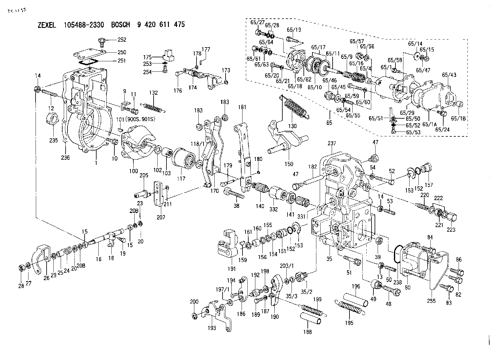
1. Remove bolts (1) and fan guard (2). 2. Loosen bolts (7), (9) and (10). Remove belts (8).3. Remove bolt (4) to clip. Remove grease line (3).4. Remove nuts (6). Remove cover (5) and the gasket. 5. Loosen bolt (12) enough to leave a gap of 3.18 mm (.125 in) between washers (11) and the fuel pump drive gear.6. Install tool (A) as shown. Tighten the stud to pull the fuel pump drive gear loose from the taper on the fuel injection pump camshaft.7. Remove tool (A), bolt (12), and washer (11). 8. Identify and disconnect wires (13).9. Remove tube assemblies (15) and (18).10. Remove two bolts (14), fuel transfer pump (17), and the O-ring seal.11. Remove bolts (16), the filter base, the gasket, and filter (19). 12. Fasten the fuel injection pump housing and governor to a hoist.13. Remove two bolts (22), three nuts (21), and the fuel injection pump housing and governor. The weight of the fuel injection pump housing and governor is 29 kg (64 lb.).14. Remove the two O-ring seals from the bottom of the fuel injection pump housing and governor. 15. Loosen screw (25). Remove two screws (26), control assembly (23) and spacers (24).Install Fuel Injection Pump Housing And Governor
Start By:a. remove fuel injection linesb. remove valve cover Number 1 piston must be set at top dead center (TDC) to perform all timing procedures. The engine is seen from the flywheel end when direction of crankshaft rotation is given. 1. Remove the starter.2. Install tool (B) on flywheel housing as shown.3. To find TDC for No. 1 piston;a. Turn the flywheel clockwise (opposite the direction of engine rotation) approximately 30 degrees. This removes all play from the timing gears. If you go past the bolt hole, you must repeat Step (a).b. Turn the flywheel counterclockwise until a 3/8" - 16 x 2 1/4" NC bolt (27) can be installed in the flywheel through the hole in the flywheel housing. The No. 1 and No. 6 pistons are now at top center position. The No. 1 piston is on the compression stroke when the valves of the No. 1 cylinder are closed. The rocker must be free to move up and down.4. If No. 1 piston is not on the compression stroke, remove the 3/8" - 16 x 2 1/4" NC bolt (27) and turn the flywheel 360° counterclockwise. Install the 3/8" bolt as before. The No. 1 piston is now at TDC.
Typical Example5. Install tooling (C) in the fuel injection pump housing as shown. Push on tooling (C) and turn injection pump camshaft (32). When tooling (C) engages the groove (slot) in the camshaft, the fuel injection pump is in the No. 1 piston TDC position.6. Be sure O-ring seals (28), (29), (30) and (31) are in position on the fuel injection pump housing and governor. Put clean engine oil
Keep all parts clean from contaminants. Contaminants put into the system may cause rapid wear and shortened component life.
1. Remove bolts (1) and fan guard (2). 2. Loosen bolts (7), (9) and (10). Remove belts (8).3. Remove bolt (4) to clip. Remove grease line (3).4. Remove nuts (6). Remove cover (5) and the gasket. 5. Loosen bolt (12) enough to leave a gap of 3.18 mm (.125 in) between washers (11) and the fuel pump drive gear.6. Install tool (A) as shown. Tighten the stud to pull the fuel pump drive gear loose from the taper on the fuel injection pump camshaft.7. Remove tool (A), bolt (12), and washer (11). 8. Identify and disconnect wires (13).9. Remove tube assemblies (15) and (18).10. Remove two bolts (14), fuel transfer pump (17), and the O-ring seal.11. Remove bolts (16), the filter base, the gasket, and filter (19). 12. Fasten the fuel injection pump housing and governor to a hoist.13. Remove two bolts (22), three nuts (21), and the fuel injection pump housing and governor. The weight of the fuel injection pump housing and governor is 29 kg (64 lb.).14. Remove the two O-ring seals from the bottom of the fuel injection pump housing and governor. 15. Loosen screw (25). Remove two screws (26), control assembly (23) and spacers (24).Install Fuel Injection Pump Housing And Governor
Start By:a. remove fuel injection linesb. remove valve cover Number 1 piston must be set at top dead center (TDC) to perform all timing procedures. The engine is seen from the flywheel end when direction of crankshaft rotation is given. 1. Remove the starter.2. Install tool (B) on flywheel housing as shown.3. To find TDC for No. 1 piston;a. Turn the flywheel clockwise (opposite the direction of engine rotation) approximately 30 degrees. This removes all play from the timing gears. If you go past the bolt hole, you must repeat Step (a).b. Turn the flywheel counterclockwise until a 3/8" - 16 x 2 1/4" NC bolt (27) can be installed in the flywheel through the hole in the flywheel housing. The No. 1 and No. 6 pistons are now at top center position. The No. 1 piston is on the compression stroke when the valves of the No. 1 cylinder are closed. The rocker must be free to move up and down.4. If No. 1 piston is not on the compression stroke, remove the 3/8" - 16 x 2 1/4" NC bolt (27) and turn the flywheel 360° counterclockwise. Install the 3/8" bolt as before. The No. 1 piston is now at TDC.
Typical Example5. Install tooling (C) in the fuel injection pump housing as shown. Push on tooling (C) and turn injection pump camshaft (32). When tooling (C) engages the groove (slot) in the camshaft, the fuel injection pump is in the No. 1 piston TDC position.6. Be sure O-ring seals (28), (29), (30) and (31) are in position on the fuel injection pump housing and governor. Put clean engine oil
Have questions with 016010-0540?
Group cross 016010-0540 ZEXEL
Isuzu
016010-0540
9 421 617 076
1157290230
LOCKING WASHER
016010-0540
9 421 617 076
9091854040
LOCKING WASHER
Hino
016010-0540
9 421 617 076
6073134370
LOCKING WASHER
016010-0540
9 421 617 076
6073134770
LOCKING WASHER
016010-0540
9 421 617 076
221201070A
LOCKING WASHER
016010-0540
9 421 617 076
221241080A
LOCKING WASHER
016010-0540
9 421 617 076
221241070A
LOCKING WASHER
016010-0540
9 421 617 076
S221241070A
LOCKING WASHER
Mitsubishi
016010-0540
9 421 617 076
ME705249
LOCKING WASHER
Nissan
016010-0540
9 421 617 076
0092250410
LOCKING WASHER
016010-0540
9 421 617 076
1933290001
LOCKING WASHER
Nissan-Diesel
016010-0540
9 421 617 076
1933290001
LOCKING WASHER
Mazda
016010-0540
9 421 617 076
S21324397
LOCKING WASHER
Ishikawajima-S
016010-0540
9 421 617 076
1312964370
LOCKING WASHER
M.Bishi-Hi.-Nag
016010-0540
9 421 617 076
EZ40060XX175
LOCKING WASHER
Bosch
016010-0540
9 421 617 076
2916083007
LOCKING WASHER