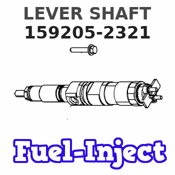
Information lever shaft
BOSCH
9 421 610 890
9421610890
ZEXEL
159205-2321
1592052321
ISUZU
1157298200
1157298200
Rating:
Include in ###:
Cross reference number
Zexel num
Bosch num
Firm num
Name
159205-2321
9 421 610 890
1157298200 ISUZU
LEVER SHAFT
C 14GJ SHAFT GOV
C 14GJ SHAFT GOV
159205-2321
9 421 610 890
223381430A HINO
LEVER SHAFT
C 14GJ SHAFT GOV
C 14GJ SHAFT GOV
159205-2321
9 421 610 890
S223381430A HINO
LEVER SHAFT
A C 14GJ SHAFT GOV
A C 14GJ SHAFT GOV
159205-2321
9 421 610 890
ME723668 MITSUBISHI
LEVER SHAFT
C 14GJ SHAFT GOV
C 14GJ SHAFT GOV
159205-2321
9 421 610 890
1931089TA0 NISSAN
LEVER SHAFT
C 14GJ SHAFT GOV
C 14GJ SHAFT GOV
159205-2321
9 421 610 890
1920454T60 NISSAN-DIESEL
LEVER SHAFT
C 14GJ SHAFT GOV
C 14GJ SHAFT GOV
Information:
Illustration 4 g01341045
(6) Temperature Sensor
(7) Pressure Sensor
Mount the 271-7350 Warning Indicator Module Gp in a place that is easy to view. Ensure that the ambient temperature is below 45 °C (113 °F), and ensure that the Warning Indicator Module is not directly exposed to high pressure steam cleaning, solvents, the battery off gas, or electrical discharge. Note: The LED display panel may be installed in the cab of the vehicle.
Illustration 5 g01341118
(8) LED display panel
(9) ECM Installation for the Wiring Harness
The 274-7578 Monitor Electronic Control Module is provided with a 307-5521 Wire Harness.
Connect the 70 pin AMP to the ECM using a 160-7690 Connector Plug As. Tighten the Connector Screw for the ECM to 6 1 N m (4 0.73 lb ft).
Locate a 12 VDC or 24 VDC power supply that is always available even when the key is turned "OFF".
Connect the power wires from the wiring harness to the power supply. Install a 15 AMP fuse in this circuit. If an additional wire must be spliced, use a 14 gauge wire.
Attach the appropriate connectors to the pressure sensor, the temperature sensor, and the lamp group. Note: The service tool that is used in this installation is Caterpillar Electronic Technician (CAT ET). The service tool connector is a 9 pin Deutsch connector that contains the CDL (Caterpillar Data Link)/ATA, CAN/J1939, and power. A connection from the 274-7578 Monitor Electronic Control Module to the PC requires a Caterpillar Communications adapter, which connects to the PC via a serial port.The service tool (CAT ET) supports the following functions:
Download and review active alarms and logged alarms
Clear active alarms
View the data in real time.
Flash the diagnostic module.
Provide the capability for the user to configure certain parameters.Software Configuration
Refer to Systems Operation, Troubleshooting, Testing and Adjusting, KENR6695 for a description of controllable parameters and operation instructions.Once the 274-7578 Monitor Electronic Control Modulehas power, the 274-7578 Monitor Electronic Control Module will begin monitoring the pressure sensors and the temperature sensors.
Check whether CAT ET is configured with English or Metric units.
Set CAT ET to Metric units if a Metric unit is not already selected. Specifications
Table 3
System Requirements
Requirements for 12VDC or 24VDC System Value Notes
Operating Voltage Minimum +9V Minimum continuous operating voltage without damage to the ECM
Maximum Operating Voltage +32V Maximum continuous operating voltage without damage to the ECM
The voltage is over the maximum voltage that is allowed (two minutes continuous). +80V At 25 °C (77 °F)
Reverse Voltage (one hour) -32V At 85 °C (185 °F)
Power up voltage for the ECM +9V The minimum voltage for the ECM to internally run. Operating the engine at this voltage will cause the damage to the ECM.
The maximum current draw with key switch off 10mA
Maximum current draw with zero engine speed and no loads being driven 500mA
Maximum continuous operating current draw 10A This highly dependent upon the number and type of loads driven by the ECM
Recommended size for the Battery Fuse. 15A
Table 4
Operating Conditions
Thermal Conditions Vibrations Humidity Tolerance Salt Spray Tolerance Moisture Leakage Chemical Splash Immunity Electrostatic Environment
Operating Temperature Range:
Have questions with 159205-2321?
Group cross 159205-2321 ZEXEL
Isuzu
Mitsubishi
Nissan-Diesel
Isuzu
159205-2321
9 421 610 890
1157298200
LEVER SHAFT
Hino
159205-2321
9 421 610 890
223381430A
LEVER SHAFT
159205-2321
9 421 610 890
S223381430A
LEVER SHAFT
Mitsubishi
159205-2321
9 421 610 890
ME723668
LEVER SHAFT
Nissan
159205-2321
9 421 610 890
1931089TA0
LEVER SHAFT
Nissan-Diesel
159205-2321
9 421 610 890
1920454T60
LEVER SHAFT