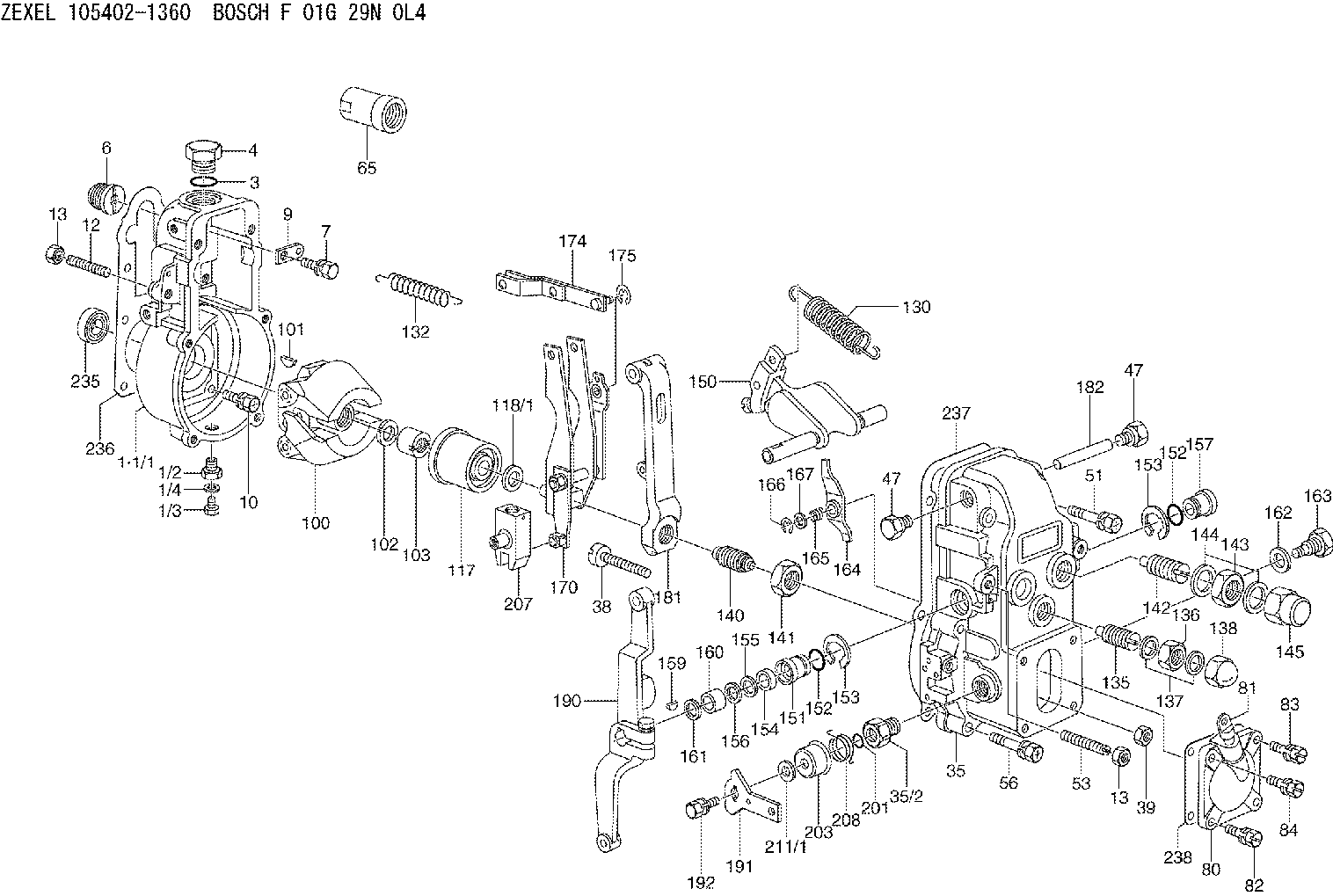
Information lever group
BOSCH
9 421 621 168
9421621168
ZEXEL
154326-8920
1543268920
MITSUBISHI
ME755389
me755389

Rating:
Include in ###:
Cross reference number
Zexel num
Bosch num
Firm num
Name
154326-8920
9 421 621 168
ME755389 MITSUBISHI
LEVER GROUP
C 14GJ LEVER ASSY GOV
C 14GJ LEVER ASSY GOV
Information:
Introduction
Do not perform any procedure in this Special Instruction until you have read the information and you understand the information.Required Tools
Table 1
Part Number Part Name Qty
- Flat-head screwdriver 1 Replacement Procedure
Illustration 1 g06099930
(1) Connector housing
(2) DCU
(3) Camlock connectors
Locate connector housings (1) on DCU (2). Disconnect the connectors from the DCU.
Illustration 2 g06099944
(1) Connector housing
(3) Camlock connector
(A) Flat-head screwdriver
Use a flat-head screwdriver (A) to pry the tab on the side of connector housing (1) up gently. Pull out on the camlock connector to disengage the locking tab.
Flip connector housing (1) over to the opposite side. Use a flat-head screwdriver (A) to pry the tab on the side of the connector housing up gently. Pull out on the camlock connector to disengage the locking tab.
Illustration 3 g06099938
(1) Connector housing
(3) Camlock connector
Remove camlock connector (3) from connector housing (1).
To install the new camlock connector (3), slide the camlock connector into connector housing (1). Once the camlock is pushed past the locking tabs, the camlock connector will be held in place.