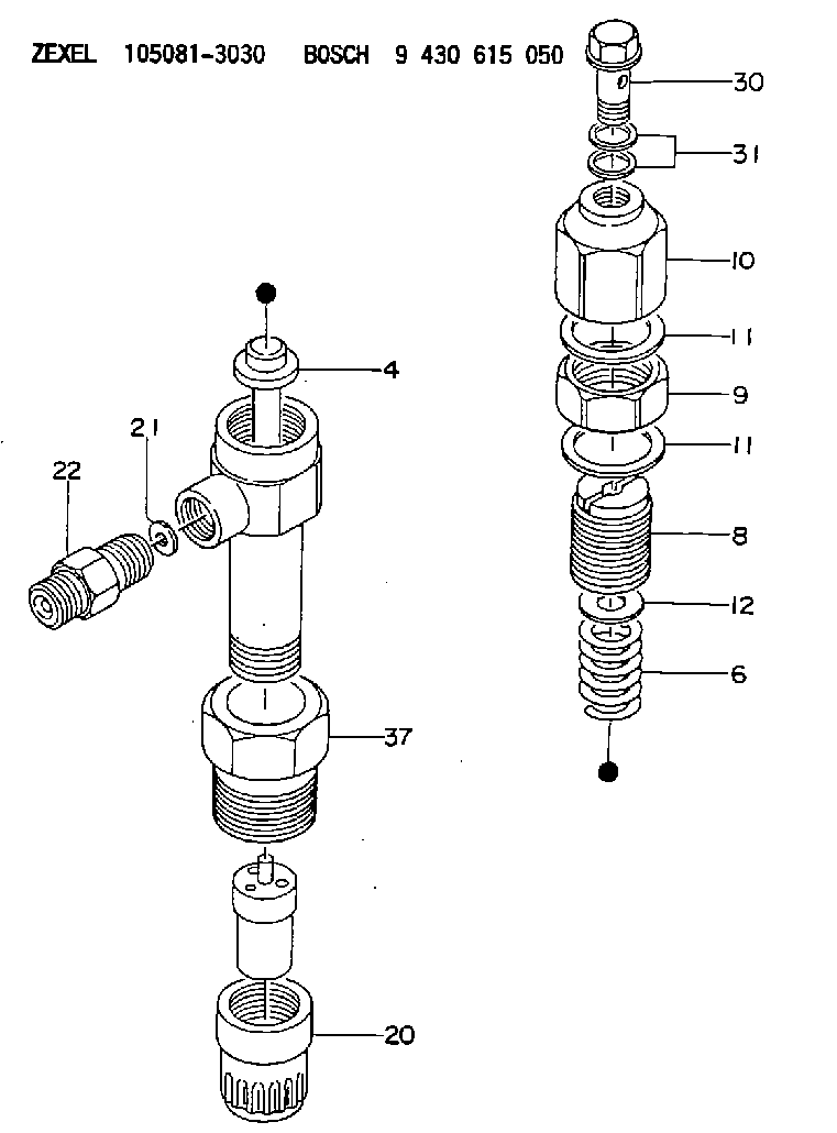
Information inlet union
BOSCH
9 431 610 167
9431610167
ZEXEL
150643-4820
1506434820
ISUZU
9153510070
9153510070

Rating:
Compare Prices: .
As an associate, we earn commssions on qualifying purchases through the links below

$28.88
08 Jun 2021
US: EFI Equipment and Pa
JOINT FOR ALLIS-CHALMERS: 9-15351-007-0
Parts Express ALLIS-CHALMERS || All Brand new & rebuilt items comes with 1 year warranty. || JOINT. Category: ALLIS-CHALMERS FORKLIFT PARTS. This part can also be found under the following part numbers: AC9-15351-007-0 9-15351-007-0 ALLIS CHALMERS/TUSK AC 9-15351-007-0 ALLIS CHALMERS/TUSK9-15351-007-0 AC9153510070 AC 9153510070 Â 9-15351-007-0 ALLIS CHALMERS/TUSK 9153510070 ALLIS CHALMERS/TUSK9153510070 Â 9153510070. All Brand new & rebuilt items comes with 1 year warranty.
Parts Express ALLIS-CHALMERS || All Brand new & rebuilt items comes with 1 year warranty. || JOINT. Category: ALLIS-CHALMERS FORKLIFT PARTS. This part can also be found under the following part numbers: AC9-15351-007-0 9-15351-007-0 ALLIS CHALMERS/TUSK AC 9-15351-007-0 ALLIS CHALMERS/TUSK9-15351-007-0 AC9153510070 AC 9153510070 Â 9-15351-007-0 ALLIS CHALMERS/TUSK 9153510070 ALLIS CHALMERS/TUSK9153510070 Â 9153510070. All Brand new & rebuilt items comes with 1 year warranty.
Include in ###:
Cross reference number
Zexel num
Bosch num
Firm num
Name
150643-4820
9 431 610 167
9153510070 ISUZU
INLET UNION
C 53PZ INLET CONNECTOR NH parts NH
C 53PZ INLET CONNECTOR NH parts NH
150643-4820
9 431 610 167
62153590130 ISEKI
INLET UNION
C 53PZ INLET CONNECTOR NH parts NH
C 53PZ INLET CONNECTOR NH parts NH
Information:
start by:a) remove turbocharger 1. Put the turbocharger in position on tool (A). Move tool (A) so the compressor housing is up. 2. For installation alignment purposes, make a mark on the center housing and turbine housing. Bend down the lock plates and remove six bolts (1). If some of the bolts are hard to remove, put penetrating oil on the bolt and hit the flat of the bolt head with a punch and hammer. 3. Lift the center housing and turbine wheel out of the turbine housing. If the assembly is hard to get apart, lift up on the compressor housing and hit the turbine housing with a soft hammer. 4. Remove clamp (2) from the compressor housing. For installation alignment purposes, make a mark on the center housing and the compressor housing. 5. Lift the center housing out of the compressor housing. Put the turbine wheel in tooling (B).6. Remove nut (3) with a universal socket. Remove O-ring (4).
Do not put a side force on the shaft when the nut is removed.
7. Heat the compressor wheel in oil for no more than ten minutes. The temperature of the oil must be 350° 25°F (176° 14°C).
The bearing heating oil used to heat the compressor wheel must have a flash point above 400°F (204°C).
8. Immediately after removing the compressor wheel from the oil, put the center housing in a press and use tooling (C) and (D) to remove the compressor wheel and center housing from the shaft.
Do not let the turbine wheel hit the bottom of the press.
9. Put the turbine wheel in tooling (B) and remove ring (6) and shroud (5). 10. Remove three bolts (7) and the three lock plates from center housing (8). 11. Remove plate (9) with tool (E). Remove the O-ring from plate (9). 12. Remove spacer (10) from plate (9). Remove collar (11) and thrust bearing (15). Remove bearing (12) and put a long dye mark on the top face of the bearing. Use tool (F) to remove rings (16) and (13). Remove bearing (17) and put a short dye mark on the top face of the bearing. Remove ring (14) with tool (F). The dye marks are for identification when installing the bearings.13. Inspect all parts and install new parts if needed. Use Special Instruction Form No. GMG00153-01, Turbocharger Reconditioning, Form No. FEG45138, Analyzing Turbocharger Failure and Video Tape JEG08054 (1/2 inch reel) (JEG09052-cassette), Turbocharger Reconditioning I (AIRESEARCH) for references.Assemble Turbocharger
1. Make sure all oil passages are open and clean. Put clean engine oil on all parts before assembly. 2. Install ring (3) with tool (A). Install bearing (4) with the short dye mark up. Install rings (2) and (1) with tool (A). Rings (1), (2) and (3) must be installed with the round edge toward the bearing. 3. Install shroud (5) on the turbine shaft. Install ring (6). Put 6V2055 High Vacuum Grease on ring (6) and fill the groove for the ring to one half depth all
Have questions with 150643-4820?
Group cross 150643-4820 ZEXEL
Isuzu
150643-4820
9 431 610 167
9153510070
INLET UNION
Iseki
150643-4820
9 431 610 167
62153590130
INLET UNION