Information inlet union
BOSCH
9 461 613 890
9461613890
ZEXEL
146607-7620
1466077620
ISUZU
8943175140
8943175140
Rating:
Include in ###:
Number on scheme 247

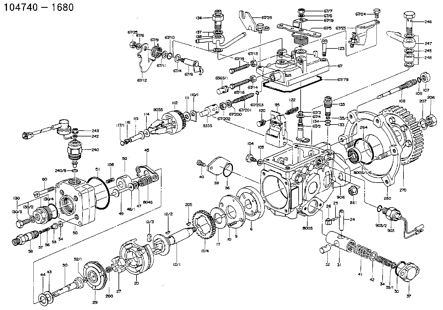
1047401680
as INLET UNION
IN B3
1047401780
as INLET UNION
1047411442
as INLET UNION
IN B3
1047411501
as INLET UNION
1047416570
as INLET UNION
IN B3
1047416571
as INLET UNION
Cross reference number
Zexel num
Bosch num
Firm num
Name
146607-7620
9 461 613 890
8943175140 ISUZU
INLET UNION
C 11FV EYE parts(VE) Others
C 11FV EYE parts(VE) Others
Information:
4. Put clean engine oil on the O-ring seal, and assemble elbow (4) to drain tube (5).5. Put the gaskets in position on the block and on the turbocharger, and install the drain tube assembly. 6. Put a gasket in position between oil supply tube (6) and the turbocharger. Install oil supply tube (6).Disassemble Turbocharger (TV72 & TV78)
START BY:a. remove turbocharger (TV72 & TV78) 1. Install the turbocharger in tool group (A). Put alignment marks on the three housings of the turbocharger for correct installation and alignment at assembly. Remove "V" clamp (2) and compressor housing (1). 2. Remove "V" clamp (3). Remove cartridge housing (5) from turbine housing (4).
When the nut is loosened, do not put a side force on the shaft. This can result in a bent shaft.
3. Install tool (C) in tool (B), and put the cartridge assembly in tool (C) as shown. Use tool (D) to remove the nut that holds compressor wheel (6). 4. Put the cartridge assembly in tool (E), and use a press (if necessary) to remove compressor wheel (6) from the turbine wheel and shaft assembly. Do not let the turbine wheel and shaft assembly fall during removal of the compressor wheel from the turbine wheel and shaft. 5. Remove seal ring (7) and shroud (8) from turbine wheel and shaft assembly (9). 6. Bend the tabs of the locks from bolts (10), and remove the bolts and locks.7. Remove backplate assembly (11) from the cartridge housing. 8. Remove spacer (12) from backplate assembly (11). Remove seal rings (13) from spacer (12). 9. Remove collar (14), thrust bearing (15) and O-ring seal (16) from the cartridge housing. 10. Remove top bearing (17) and the washer from the cartridge housing. Put a long dye mark on the top face of bearing (17).11. Use tool (F), and remove the two rings that hold the top and bottom bearings in position. Remove the bottom bearing and washer. Put a short dye mark on the bearing. The dye marks are used for identification of the bearings when they are installed.12. Use tool (F), and remove the last ring that holds the bottom bearing in position from the cartridge housing.13. Check all the parts of the turbocharger for damage. If the parts are damaged, use new parts for replacement. See Special Instruction Form No. SMHS6854 for Turbocharger Reconditioning. Also see Guidelines For Reuseable Parts, Form No. SEBF8018.Assemble Turbocharger (TV72 & TV78)
1. Make sure that all of the oil passages in the turbocharger cartridge housing are clean and free of dirt and foreign material.2. Put clean engine oil on all parts of the cartridge assembly.
Rings (1), (4) and (5) must be installed with the round edge of the outside diameter of the rings toward the bearings.
3. Install ring (4) in the cartridge
Have questions with 146607-7620?
Group cross 146607-7620 ZEXEL
Isuzu
146607-7620
9 461 613 890
8943175140
INLET UNION