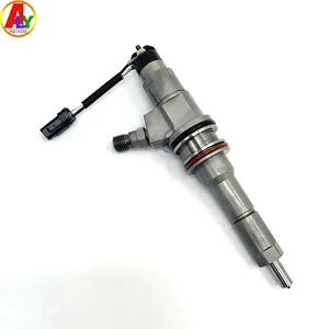
Information injector
BOSCH
0 445 120 006
0445120006
ZEXEL
107755-0030
1077550030

Rating:
Compare Prices: .
As an associate, we earn commssions on qualifying purchases through the links below

1pc 0445120006 ME355278 MGKBOQIF
MGKBOQIF
MGKBOQIF

4pcs/lot Common Rail Injector Control Valve F 00R J00 375/F00RJ00375/FOORJ00375 for B osch Injector 0445120006 for M itsubishi
Generic
Generic

0445120006 Diesel Common Rail Fuel Injector Nozzle Compatible With Mercedes-Benz and Compatible With Mitsubishi 6M60 6M70 ME355278
GUYQVRLMP 1. Precision structure, stable and durable, reduce failure. || 2. Precise control of fuel injection, more stable power output. || 3. High pressure injection, fuel atomization, combustion more efficient. || 4. Quickly respond to engine requirements, adjust the fuel injection at any time. || 5. Make sure the part number is the same as yours before ordering.
GUYQVRLMP 1. Precision structure, stable and durable, reduce failure. || 2. Precise control of fuel injection, more stable power output. || 3. High pressure injection, fuel atomization, combustion more efficient. || 4. Quickly respond to engine requirements, adjust the fuel injection at any time. || 5. Make sure the part number is the same as yours before ordering.
You can express buy:

USD 12.59
29-06-2025
29-06-2025
F00RJ00375, F 00R J00 375 For Common Rail Injector 0445120006 Fuel Injection Valve Diesel Engine Parts Hot Sale THYHA14S38
USD 5.8
29-06-2025
29-06-2025
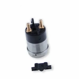
Made In China F00RJ02697 Fuel Injector Solenoid Valve OE 5010477370 For 0445120003 0445120455 0445120004 0445120006 Injector
USD 158.42
25-06-2025
25-06-2025
ALYTEST 1PCS 6m70 Spare Parts Diesel ME35527 0 445 120 006 0445120006 Fuel Injector for Mitsubishi Fuso Engine
Images:
USD 32.56

[22-Jun-2025]
USD 128.8

[21-Jun-2025]
USD 101.85
[14-Jun-2025]
USD 120.03

[14-Jun-2025]
Cross reference number
Zexel num
Bosch num
Firm num
Name
107755-0030
0 445 120 006
INJECTOR
* C
* C
107755-0030
0 445 120 006
0445120006 BOSCH
INJECTOR
C
C
Information:
1. Install the turbocharger on tool (A) as shown.2. Put alignment marks on three housings of the turbocharger for correct alignment during assembly. Loosen clamp (2), and remove the clamp and housing (1) from housing assembly (3). 3. Loosen clamp (4), and remove housing assembly (3) from housing (5). 4. Put the cartridge group in position in tool (B) as shown.
When the nut is loosened, do not put a side force on the shaft. This can result in a bent shaft.
5. Use a 5S9566 Sliding T-Wrench and a universal socket (6) to remove the nut that holds the compressor wheel to the wheel assembly.6. Remove compressor wheel (7) and the shims from wheel assembly (8).7. Remove housing assembly (3) from wheel assembly (8). 8. Remove ring (9) and backplate (10) from wheel assembly (8). 9. Use tool (C), and remove snap ring (11) from housing assembly (3). 10. Remove insert (12) and sleeve (13) from housing assembly (3). 11. Remove ring (14) from sleeve (13). 12. Remove two screws (15) and deflector (16) from housing assembly (3). 13. Remove ring (18) and bearing assembly (17) from the housing assembly. 14. Remove sleeve (19) and ring (20) from the housing assembly. 15. Remove O-ring seal (23) from the housing assembly.16. Use tool (D), and remove snap ring (22) from the housing assembly.17. Remove bearing (21). Remove the snap ring behind the bearing with tool (D). 18. Use tool (D), and remove snap ring (25) from the housing assembly.19. Remove bearing (24). Remove the snap ring behind the bearing with tool (D).20. Check all the parts of the turbocharger for damage. If the parts are damaged, use new parts for replacement. See Special Instruction, Form No. SMHS6854 for Turbocharger Reconditioning. Also see Guidelines For Reusable Parts, Form No. SEBF8018.Assemble Turbocharger
1. Make sure that all of the oil passages in the turbocharger cartridge housing are clean and free of dirt and foreign material. Do not put oil on any parts of the turbocharger until after the compressor wheel has been installed. After the turbocharger has been assembled, pour clean engine oil into the oil inlet of the turbocharger.
Make sure that the snap rings that hold bearings (24) and (21) in position in housing assembly (3) are installed with the round edge of the outside diameter toward the bearing.
2. Install the snap ring behind bearing (24) with tool (D).3. Install bearing (24) in housing assembly (3).4. Use tool (D), and install snap ring (25) in the housing assembly. 5. Install the snap ring behind bearing (21) with tool (D).6. Install bearing (21) in the housing assembly.7. Use tool (D), and install snap ring (22) in the housing assembly. 8. Put wheel assembly (8) in position on tool (B) as shown.9. Put backplate (10) in position on the wheel assembly. Put 6V2055 High Vacuum Grease
Have questions with 107755-0030?
Group cross 107755-0030 ZEXEL
Bosch
107755-0030
0 445 120 006
INJECTOR
Bosch
107755-0030
0 445 120 006
0445120006
INJECTOR