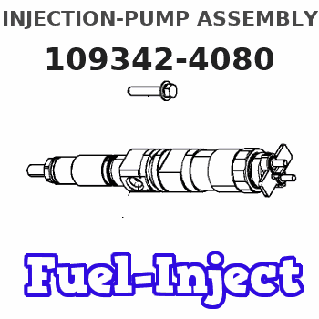
Information injection-pump assembly
BOSCH
0 470 504 046
0470504046
ZEXEL
109342-4080
1093424080
NISSAN-DIESEL
16700VX101
16700vx101
Rating:
Compare Prices: .
As an associate, we earn commssions on qualifying purchases through the links below

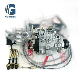
Car fuel pump assembly, High Pressure Diesel Injection Fuel Pump 16700VG100,16700VX101,109342-4026,109342-4080,0470504046
ZTUVUNVA The design of the oil outlet is exquisite and reasonable, which avoids carbon deposition at the oil outlet and effectively prolongs the service life. || Reduce fuel consumption, improve jitter and accelerate smoothly. || The oil meter is accurate, which can solve the problems of abnormal oil consumption, misfire and no power. || Solve problems such as abnormal fuel meter data. || Sufficient oil return flow ensures stable pressure and sufficient cooling of the fuel system.
ZTUVUNVA The design of the oil outlet is exquisite and reasonable, which avoids carbon deposition at the oil outlet and effectively prolongs the service life. || Reduce fuel consumption, improve jitter and accelerate smoothly. || The oil meter is accurate, which can solve the problems of abnormal oil consumption, misfire and no power. || Solve problems such as abnormal fuel meter data. || Sufficient oil return flow ensures stable pressure and sufficient cooling of the fuel system.

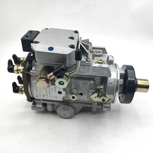
High Pressure Fuel Pump Diesel Injection 16700VG100,16700VX101,109342-4026,109342-4080,0470504046
OfkZynodor Part Name:High Pressure Fuel Pump Diesel Injection || Part Number: 16700VG100,16700VX101,109342-4026,109342-4080,0470504046 || Application:High Pressure Fuel Pump Diesel Injection 16700VG100,16700VX101,109342-4026,109342-4080,0470504046 || Attention:Please make sure to carefully compare the photos and check the part numbers before making the purchase. If you are unable to confirm your engine model or part number, please leave us a message and we will assist you in confirming that the product you purchase is the one you need. || NOTE:Your order is not merely a single purchase but the beginning of a cooperative journey, aiming to ensure the safe and smooth operation of your vehicle. We are proud to offer you reliable precision engineering components and unparalleled services.
OfkZynodor Part Name:High Pressure Fuel Pump Diesel Injection || Part Number: 16700VG100,16700VX101,109342-4026,109342-4080,0470504046 || Application:High Pressure Fuel Pump Diesel Injection 16700VG100,16700VX101,109342-4026,109342-4080,0470504046 || Attention:Please make sure to carefully compare the photos and check the part numbers before making the purchase. If you are unable to confirm your engine model or part number, please leave us a message and we will assist you in confirming that the product you purchase is the one you need. || NOTE:Your order is not merely a single purchase but the beginning of a cooperative journey, aiming to ensure the safe and smooth operation of your vehicle. We are proud to offer you reliable precision engineering components and unparalleled services.
You can express buy:
USD 822.61
25-06-2025
25-06-2025
Mechanical Fuel Injection Pump Fits for Nissan YD22 YD25 ZD30 0470504034 16700-VG100 0470504046 16700VG100 Patrol Terrano 3.0
USD 3430.89
19-05-2025
19-05-2025
VP44 Diesel injector pump fuel Injection Pump 0470504046 16700VX101 109342-4080 For NISSAN PATROL GR 3.0DTI
Images:
USD 3430.89

[19-May-2025]
USD 1777.91

[19-May-2025]
USD 2208.03

[04-May-2025]
Components :
| 0. | INJECTION-PUMP ASSEMBLY | 109342-4080 |
| 1. | _ | |
| 2. | FUEL INJECTION PUMP | 109242-4051 |
| 3. | NUMBER PLATE | |
| 4. | _ | |
| 5. | CAPSULE | |
| 6. | ADJUSTING DEVICE | |
| 7. | NOZZLE AND HOLDER ASSY | 105118-7982 |
| 8. | Nozzle and Holder | |
| 9. | Open Pre:MPa(Kqf/cm2) | 19.0{194}/37.5{382} |
| 10. | NOZZLE-HOLDER | |
| 11. | NOZZLE |
Scheme ###:
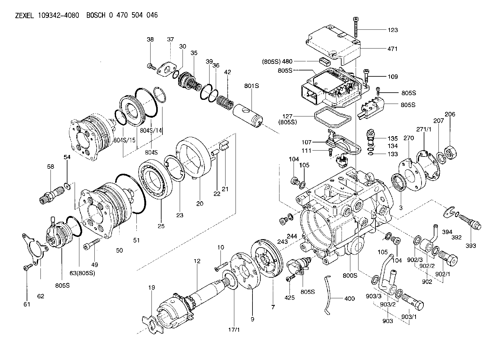
| 3. | [1] | 149351-0201 | PACKING RING |
| 7. | [1] | 149050-0220 | SUPPLY PUMP |
| 9. | [1] | 149055-0000 | SUPPORT RING |
| 10. | [4] | 149330-2000 | TORX SCREW |
| 12. | [1] | 149100-0520 | DRIVE SHAFT |
| 17/1. | [1] | 149110-0000 | SHIM D42.5627.1T2.2 |
| 17/1B. | [1] | 149110-0100 | SHIM D42.5&27.1T2.3 |
| 17/1C. | [1] | 149110-0200 | SHIM D42.5&27.1T2.4 |
| 17/1D. | [1] | 149110-0300 | SHIM D42.5&27.1T2.5 |
| 17/1E. | [1] | 149110-0400 | SHIM D42.5&27.1T2.6 |
| 17/1F. | [1] | 149110-0500 | SHIM D42.5&27.1T2.7 |
| 17/1G. | [1] | 149110-0600 | SHIM D42.5&27.1T2.8 |
| 17/1H. | [1] | 149110-0700 | SHIM D42.5&27.1T2.9 |
| 17/1I. | [1] | 149110-0800 | SHIM D42.5&27.1T3.0 |
| 17/1J. | [1] | 149110-0900 | SHIM D42.5&27.1T3.1 |
| 17/1K. | [1] | 149110-1000 | SHIM D42.5&27.1T3.2 |
| 17B/1. | [1] | 149110-1200 | SHIM D42.5&27.1T2.2 |
| 17B/1B. | [1] | 149110-1300 | SHIM D42.5&27.1T2.3 |
| 17B/1C. | [1] | 149110-1400 | SHIM D42.5&27.1T2.4 |
| 17B/1D. | [1] | 149110-1500 | SHIM D42.5&27.1T2.5 |
| 17B/1E. | [1] | 149110-1600 | SHIM D42.5&27.1T2.6 |
| 17B/1F. | [1] | 149110-1700 | SHIM D42.5&27.1T2.7 |
| 17B/1G. | [1] | 149110-1800 | SHIM D42.5&27.1T2.8 |
| 17B/1H. | [1] | 149110-1900 | SHIM D42.5&27.1T2.9 |
| 17B/1I. | [1] | 149110-2000 | SHIM D42.5&27.1T3.0 |
| 17B/1J. | [1] | 149110-2100 | SHIM D42.5&27.1T3.1 |
| 17B/1K. | [1] | 149110-2200 | SHIM D42.5&27.1T3.2 |
| 19. | [1] | 149111-0000 | DRIVER DISC |
| 20. | [1] | 149120-0120 | CAM RING |
| 21. | [2] | 149112-0200 | ROLLER SHOE |
| 22. | [2] | 149113-0300 | ROLLER |
| 23. | [1] | 149111-0100 | PLATE |
| 25. | [1] | 149114-0000 | BEARING PLATE |
| 30. | [1] | 149350-3300 | O-RING |
| 35. | [1] | 149170-0022 | HYDRAULIC STOPPER |
| 36. | [1] | 149350-3400 | O-RING |
| 37. | [1] | 149180-0300 | CLOSING COVER |
| 38. | [2] | 149330-2900 | TORX BOLT |
| 39. | [1] | 149350-1700 | SEAL RING |
| 42. | [1] | 149164-0000 | COILED SPRING |
| 49. | [4] | 149330-3900 | TORX BOLT |
| 50. | [1] | 149200-0921 | HYDRAULIC HEAD |
| 51. | [3] | 149350-2000 | O-RING |
| 54. | [4] | 149313-2700 | GASKET |
| 58. | [4] | 149305-0020 | RESTRICTION |
| 61. | [3] | 149330-3400 | TORX BOLT |
| 62. | [1] | 149436-0100 | PLATE |
| 63. | [1] | 149350-1900 | O-RING |
| 104. | [2] | 149330-3500 | HEX-SOCKET-HEAD CAP SCREW |
| 104. | [2] | 149330-3500 | HEX-SOCKET-HEAD CAP SCREW |
| 105. | [2] | 149443-0200 | GASKET |
| 105. | [2] | 149443-0200 | GASKET |
| 107. | [1] | 149403-0320 | SENSOR |
| 107B. | [1] | 149403-0520 | SENSOR |
| 109. | [3] | 149330-1600 | TORX BOLT |
| 111. | [2] | 149330-0501 | TORX SCREW |
| 123. | [5] | 149330-3900 | TORX BOLT |
| 127. | [1] | 149350-2800 | SEAL RING |
| 133. | [1] | 149350-3500 | O-RING |
| 134. | [1] | 149350-3600 | O-RING |
| 135. | [1] | 149060-0520 | CONTROL VALVE |
| 206. | [1] | 149330-2500 | UNION NUT |
| 207. | [1] | 149412-0100 | PLAIN WASHER |
| 243. | [1] | 149330-3500 | HEX-SOCKET-HEAD CAP SCREW |
| 244. | [1] | 149443-0200 | GASKET |
| 270. | [1] | 149411-2600 | COUPLING PLATE |
| 271/1. | [1] | 149411-1300 | SHIM T0.5 |
| 271/1B. | [1] | 149411-1400 | SHIM T0.6 |
| 271/1C. | [1] | 149411-1500 | SHIM T0.7 |
| 271/1D. | [1] | 149411-1600 | SHIM T0.8 |
| 271/1E. | [1] | 149411-1700 | SHIM T0.9 |
| 271/1F. | [1] | 149411-1800 | SHIM T1.0 |
| 271/1G. | [1] | 149411-1900 | SHIM T1.1 |
| 271/1H. | [1] | 149411-2000 | SHIM T1.2 |
| 271/1I. | [1] | 149411-2100 | SHIM T1.3 |
| 271/1J. | [1] | 149411-2200 | SHIM T1.4 |
| 271/1K. | [1] | 149411-2300 | SHIM T1.5 |
| 271B/1. | [1] | 149411-4000 | SHIM T0.5 |
| 271B/1B. | [1] | 149411-4100 | SHIM T0.6 |
| 271B/1C. | [1] | 149411-4200 | SHIM T0.7 |
| 271B/1D. | [1] | 149411-4300 | SHIM T0.8 |
| 271B/1E. | [1] | 149411-4400 | SHIM T0.9 |
| 271B/1F. | [1] | 149411-4500 | SHIM T1.0 |
| 271B/1G. | [1] | 149411-4600 | SHIM T1.1 |
| 271B/1H. | [1] | 149411-4700 | SHIM T1.2 |
| 271B/1I. | [1] | 149411-4800 | SHIM T1.3 |
| 271B/1J. | [1] | 149411-4900 | SHIM T1.4 |
| 271B/1K. | [1] | 149411-5000 | SHIM T1.5 |
| 392. | [1] | 149350-3700 | O-RING |
| 393. | [1] | 149419-0600 | BLEEDER SCREW |
| 394. | [1] | 149420-0001 | INTERMEDIATE PLATE |
| 400. | [1] | 149460-1300 | CABLE CRAMP |
| 425. | [2] | 149330-3300 | TORX BOLT |
| 471. | [1] | 149410-0000 | COVER |
| 480. | [1] | 149350-3800 | SEAL RING |
| 800S. | [1] | 149480-0220 | SERVICE PARTS GROUP |
| 801S. | [1] | 149481-0420 | PARTS SET |
| 804S. | [1] | 149483-0020 | PARTS SET |
| 804S/14. | [1] | 149350-1800 | O-RING |
| 804S/15. | [1] | 149350-1900 | O-RING |
| 805S. | [1] | 149482-0220 | PARTS SET |
| 805S. | [1] | 149482-0220 | PARTS SET |
| 805S. | [1] | 149482-0220 | PARTS SET |
| 805S. | [1] | 149482-0220 | PARTS SET |
| 805S. | [1] | 149482-0220 | PARTS SET |
| 805S. | [1] | 149482-0220 | PARTS SET |
| 805S. | [1] | 149482-0220 | PARTS SET |
| 902. | [1] | 149433-0220 | OUTLET PIPE ASSY |
| 902/1. | [1] | 149070-0120 | OVER FLOW VALVE |
| 902/2. | [1] | 146669-4420 | INLET UNION |
| 902/3. | [2] | 149350-2700 | FLAT SEAL RING |
| 903. | [1] | 149428-0520 | INLET PIPE |
| 903/1. | [1] | 149330-0000 | EYE BOLT |
| 903/2. | [1] | 149425-0020 | INLET UNION |
| 903/3. | [2] | 149350-2600 | FLAT SEAL RING |
Include in #2:
109342-4080
as INJECTION-PUMP ASSEMBLY
Cross reference number
Zexel num
Bosch num
Firm num
Name
0 470 504 046
16700VX101 NISSAN-DIESEL
INJECTION-PUMP ASSEMBLY
ZD30ETI * K 13CJ INJECTION PUMP ASSY VP44 VP44
ZD30ETI * K 13CJ INJECTION PUMP ASSY VP44 VP44
Information:
1. Loosen the clamps on hose (3), remove nuts (2) and remove temperature regulator housing (1) and the gasket from the cylinder head. 2. Remove bolt (5) and the nut from the bracket.3. Remove bolts (6) and (7) that hold the fuel injection lines in position. Remove fuel injection lines (4) from the engine.
Put protection caps (5F2807) and plugs (2F2990) on the injection lines and pumps to keep dirt and foreign material out of the fuel system.
4. Disconnect air lines (8) and (9) from the cylinder head. 5. Remove two locks and bolts (10). Remove the dowel used for location of the rear of the camshafts and remove four bolts (12). Remove valve cover base (11) and the gasket from the cylinder head. 6. Remove bolts (14) that hold cylinder head (13) to the cylinder block. 7. Install four 3/8"-16 NC forged eyebolts in the cylinder head as shown. Fasten a hoist and remove the cylinder head. The weight of the cylinder head is 450 lb. (203 kg).8. Remove the water seals and the head gasket from the spacer plate. 9. Remove the O-ring seal from dowel (16).10. Install six 3/8"-16 NC forcing screws in spacer plate (15). Tighten the screws evenly until the spacer plate is free of the dowels. Remove spacer plate (15).11. Remove the second O-ring seal from dowel (16).Install Cylinder Head And Spacer Plate
A new spacer plate gasket must be installed when the cylinder head is removed.1. Thoroughly clean the top surface of the cylinder block, both surfaces of the spacer plate and the bottom surface of the cylinder head. 2. Put the O-ring seal in position around dowel (1).3. Put a new gasket in position on the cylinder block.
Both surfaces of the spacer plate and the top of the cylinder block must be clean. Do not use a gasket adhesive on these surfaces.
4. Install spacer plate (2) on the cylinder block. 5. Install the O-ring seal on the spacer plate around dowel (1).6. Check the cylinder liner projection. See INSTALL CYLINDER LINERS.7. Put a new cylinder head gasket and water seals in position on the spacer plate. 8. Install two 3/4"-10 NC guide bolts 11 in. long in the cylinder block. Install four 3/8"-16 NC forged eyebolts in the cylinder head. Fasten a hoist and put the cylinder head in position on the guide bolts and lower it on the engine. 9. Put 9M3710 Anti-Seize Compound on the threads of cylinder head bolts (3) and the washer faces. Install bolts (3), the washers and tighten as follows: a) Tighten the bolts in number sequence shown to a torque of 200 lb. ft. (270 N m).b) Tighten the bolts in number sequence shown to a torque of 330 10 lb. ft. (447 14 N m). c) Tighten the bolts in number sequence shown (hand tighten) to a torque of 330 10 lb. ft. (447 14 N m). 10. Put the gasket and valve cover base (4) in position on the