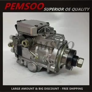
Information injection-pump assembly
BOSCH
0 470 504 029
0470504029
ZEXEL
109341-4015
1093414015
NISSAN
A6700VW201
a6700vw201

Rating:
Compare Prices: .
As an associate, we earn commssions on qualifying purchases through the links below

VP44 Fuel Injection Pump Compatible with ZD30 DTi 3.0 L Models Part Numbers 16700VW201 1093414015 A6700VW201 0470504029
BZZBAJON Equipped with precise engineering to maintain fuel delivery and improve fuel economy Compatible With your vehicle.Manufactured using materials Compatible With durability, providing under various driving conditions.Replacement part numbers include 16700VW201, 109341-4015, and 0470504029, ensuring integration with your.Ideal Compatible With both routine maintenance and necessary repairs, keeping your engine running smoothly and efficiently.Backed by stringent quality control measures to meet or
BZZBAJON Equipped with precise engineering to maintain fuel delivery and improve fuel economy Compatible With your vehicle.Manufactured using materials Compatible With durability, providing under various driving conditions.Replacement part numbers include 16700VW201, 109341-4015, and 0470504029, ensuring integration with your.Ideal Compatible With both routine maintenance and necessary repairs, keeping your engine running smoothly and efficiently.Backed by stringent quality control measures to meet or

MOMOBM Diesel Engine High-pressure Fuel Pump Fuel Pump 0470504029 Compatible for Nissan Diesel Pump,OEM 109341-4014,Fuel Delivery System
MOMOBM OEM NO:109341-4014 || PRECISION PARTS: Direct Replacement OEM High Pressure Fuel Pump || EXTRA LONG LIFE DESIGN: Rigorously Tested-Double Carbon Brushes and Corrosion Resistant Housing to meet factory specifications-No modifications required, eliminating the risk of fuel leakage || Efficient Fuel Delivery System: Reinforced stainless steel pump core + ceramic coated pistons for optimised combustion performance - Enhanced fuel atomisation to reduce engine knock and increase MPG || Plug & Play Installation Includes complete bolt-on kit (gaskets/seals/bolts)
MOMOBM OEM NO:109341-4014 || PRECISION PARTS: Direct Replacement OEM High Pressure Fuel Pump || EXTRA LONG LIFE DESIGN: Rigorously Tested-Double Carbon Brushes and Corrosion Resistant Housing to meet factory specifications-No modifications required, eliminating the risk of fuel leakage || Efficient Fuel Delivery System: Reinforced stainless steel pump core + ceramic coated pistons for optimised combustion performance - Enhanced fuel atomisation to reduce engine knock and increase MPG || Plug & Play Installation Includes complete bolt-on kit (gaskets/seals/bolts)

VP44 Fuel Injection Pump 0470504029 16700-VW201 109341-4015 16700VW201 Compatible For Nissan Urvan Truck Parts
BSZBAS OE NO. : 0470504029 16700-VW201 109341-4015 16700VW201 || Timely replacement of accessories can extend the service life of equipment || Reduce resource waste and achieve effective recycling of resources || Restore the performance of the vehicle || Enhance driving experience
BSZBAS OE NO. : 0470504029 16700-VW201 109341-4015 16700VW201 || Timely replacement of accessories can extend the service life of equipment || Reduce resource waste and achieve effective recycling of resources || Restore the performance of the vehicle || Enhance driving experience
You can express buy:
USD 2202.9
23-05-2025
23-05-2025
New 109341-4015 0470504029 Diesel VP44 Fuel Injection Pump for Nissan UD Frontier ZD30 DD 0 470 504 029 16700-VW201 A6700-VW201
Images:
USD 4115.9

[19-May-2025]
USD 3527.75

[13-May-2025]
Components :
| 0. | INJECTION-PUMP ASSEMBLY | 109341-4015 |
| 1. | _ | |
| 2. | FUEL INJECTION PUMP | 109241-4015 |
| 3. | NUMBER PLATE | |
| 4. | _ | |
| 5. | CAPSULE | |
| 6. | ADJUSTING DEVICE | |
| 7. | NOZZLE AND HOLDER ASSY | 105118-8220 |
| 8. | Nozzle and Holder | |
| 9. | Open Pre:MPa(Kqf/cm2) | 21.0{214}/39.5{403} |
| 10. | NOZZLE-HOLDER | |
| 11. | NOZZLE |
Scheme ###:
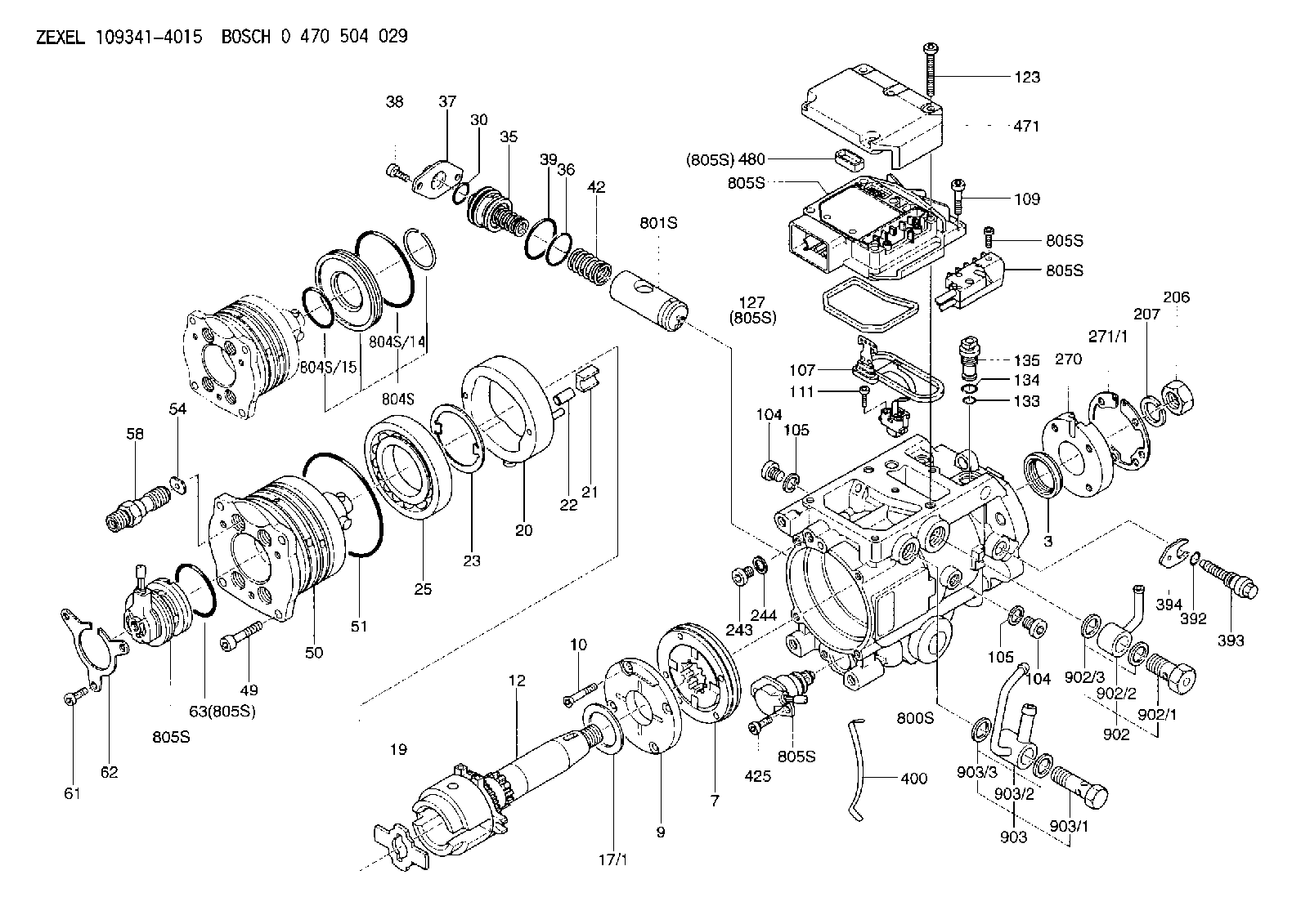
| 3. | [1] | 149351-0201 | PACKING RING |
| 7. | [1] | 149050-0220 | SUPPLY PUMP |
| 9. | [1] | 149055-0000 | SUPPORT RING |
| 10. | [4] | 149330-2000 | TORX SCREW |
| 12. | [1] | 149100-0520 | DRIVE SHAFT |
| 17/1. | [1] | 149110-0000 | SHIM D42.5627.1T2.2 |
| 17/1B. | [1] | 149110-0100 | SHIM D42.5&27.1T2.3 |
| 17/1C. | [1] | 149110-0200 | SHIM D42.5&27.1T2.4 |
| 17/1D. | [1] | 149110-0300 | SHIM D42.5&27.1T2.5 |
| 17/1E. | [1] | 149110-0400 | SHIM D42.5&27.1T2.6 |
| 17/1F. | [1] | 149110-0500 | SHIM D42.5&27.1T2.7 |
| 17/1G. | [1] | 149110-0600 | SHIM D42.5&27.1T2.8 |
| 17/1H. | [1] | 149110-0700 | SHIM D42.5&27.1T2.9 |
| 17/1I. | [1] | 149110-0800 | SHIM D42.5&27.1T3.0 |
| 17/1J. | [1] | 149110-0900 | SHIM D42.5&27.1T3.1 |
| 17/1K. | [1] | 149110-1000 | SHIM D42.5&27.1T3.2 |
| 17B/1. | [1] | 149110-1200 | SHIM D42.5&27.1T2.2 |
| 17B/1B. | [1] | 149110-1300 | SHIM D42.5&27.1T2.3 |
| 17B/1C. | [1] | 149110-1400 | SHIM D42.5&27.1T2.4 |
| 17B/1D. | [1] | 149110-1500 | SHIM D42.5&27.1T2.5 |
| 17B/1E. | [1] | 149110-1600 | SHIM D42.5&27.1T2.6 |
| 17B/1F. | [1] | 149110-1700 | SHIM D42.5&27.1T2.7 |
| 17B/1G. | [1] | 149110-1800 | SHIM D42.5&27.1T2.8 |
| 17B/1H. | [1] | 149110-1900 | SHIM D42.5&27.1T2.9 |
| 17B/1I. | [1] | 149110-2000 | SHIM D42.5&27.1T3.0 |
| 17B/1J. | [1] | 149110-2100 | SHIM D42.5&27.1T3.1 |
| 17B/1K. | [1] | 149110-2200 | SHIM D42.5&27.1T3.2 |
| 19. | [1] | 149111-0000 | DRIVER DISC |
| 20. | [1] | 149120-0020 | CAM RING |
| 21. | [2] | 149112-0200 | ROLLER SHOE |
| 22. | [2] | 149113-0300 | ROLLER |
| 23. | [1] | 149111-0100 | PLATE |
| 25. | [1] | 149114-0000 | BEARING PLATE |
| 30. | [1] | 149350-3300 | O-RING |
| 35. | [1] | 149170-0022 | HYDRAULIC STOPPER |
| 36. | [1] | 149350-3400 | O-RING |
| 37. | [1] | 149180-0300 | CLOSING COVER |
| 38. | [2] | 149330-2900 | TORX BOLT |
| 39. | [1] | 149350-1700 | SEAL RING |
| 42. | [1] | 149164-0000 | COILED SPRING |
| 49. | [4] | 149330-3900 | TORX BOLT |
| 50. | [1] | 149200-0723 | HYDRAULIC HEAD |
| 51. | [3] | 149350-2000 | O-RING |
| 54. | [4] | 149313-2700 | GASKET |
| 58. | [4] | 149300-1120 | PRESSURE-CONTROL VALVE |
| 61. | [3] | 149330-3400 | TORX BOLT |
| 62. | [1] | 149436-0100 | PLATE |
| 63. | [1] | 149350-1900 | O-RING |
| 104. | [2] | 149330-3500 | HEX-SOCKET-HEAD CAP SCREW |
| 104. | [2] | 149330-3500 | HEX-SOCKET-HEAD CAP SCREW |
| 105. | [2] | 149443-0200 | GASKET |
| 105. | [2] | 149443-0200 | GASKET |
| 107. | [1] | 149403-0320 | SENSOR |
| 107B. | [1] | 149403-0520 | SENSOR |
| 109. | [3] | 149330-1600 | TORX BOLT |
| 111. | [2] | 149330-0501 | TORX SCREW |
| 123. | [5] | 149330-3900 | TORX BOLT |
| 127. | [1] | 149350-2800 | SEAL RING |
| 133. | [1] | 149350-3500 | O-RING |
| 134. | [1] | 149350-3600 | O-RING |
| 135. | [1] | 149060-0520 | CONTROL VALVE |
| 206. | [1] | 149330-2500 | UNION NUT |
| 207. | [1] | 149412-0100 | PLAIN WASHER |
| 243. | [1] | 149330-3500 | HEX-SOCKET-HEAD CAP SCREW |
| 244. | [1] | 149443-0200 | GASKET |
| 270. | [1] | 149411-2600 | COUPLING PLATE |
| 271/1. | [1] | 149411-1300 | SHIM T0.5 |
| 271/1B. | [1] | 149411-1400 | SHIM T0.6 |
| 271/1C. | [1] | 149411-1500 | SHIM T0.7 |
| 271/1D. | [1] | 149411-1600 | SHIM T0.8 |
| 271/1E. | [1] | 149411-1700 | SHIM T0.9 |
| 271/1F. | [1] | 149411-1800 | SHIM T1.0 |
| 271/1G. | [1] | 149411-1900 | SHIM T1.1 |
| 271/1H. | [1] | 149411-2000 | SHIM T1.2 |
| 271/1I. | [1] | 149411-2100 | SHIM T1.3 |
| 271/1J. | [1] | 149411-2200 | SHIM T1.4 |
| 271/1K. | [1] | 149411-2300 | SHIM T1.5 |
| 271B/1. | [1] | 149411-4000 | SHIM T0.5 |
| 271B/1B. | [1] | 149411-4100 | SHIM T0.6 |
| 271B/1C. | [1] | 149411-4200 | SHIM T0.7 |
| 271B/1D. | [1] | 149411-4300 | SHIM T0.8 |
| 271B/1E. | [1] | 149411-4400 | SHIM T0.9 |
| 271B/1F. | [1] | 149411-4500 | SHIM T1.0 |
| 271B/1G. | [1] | 149411-4600 | SHIM T1.1 |
| 271B/1H. | [1] | 149411-4700 | SHIM T1.2 |
| 271B/1I. | [1] | 149411-4800 | SHIM T1.3 |
| 271B/1J. | [1] | 149411-4900 | SHIM T1.4 |
| 271B/1K. | [1] | 149411-5000 | SHIM T1.5 |
| 392. | [1] | 149350-3700 | O-RING |
| 393. | [1] | 149419-0600 | BLEEDER SCREW |
| 394. | [1] | 149420-0001 | INTERMEDIATE PLATE |
| 400. | [1] | 149460-1300 | CABLE CRAMP |
| 425. | [2] | 149330-3300 | TORX BOLT |
| 471. | [1] | 149410-0000 | COVER |
| 480. | [1] | 149350-3800 | SEAL RING |
| 800S. | [1] | 149480-0220 | SERVICE PARTS GROUP |
| 801S. | [1] | 149481-0320 | PARTS SET |
| 804S. | [1] | 149483-0020 | PARTS SET |
| 804S/14. | [1] | 149350-1800 | O-RING |
| 804S/15. | [1] | 149350-1900 | O-RING |
| 805S. | [1] | 149482-0020 | PARTS SET |
| 805S. | [1] | 149482-0020 | PARTS SET |
| 805S. | [1] | 149482-0020 | PARTS SET |
| 805S. | [1] | 149482-0020 | PARTS SET |
| 805S. | [1] | 149482-0020 | PARTS SET |
| 805S. | [1] | 149482-0020 | PARTS SET |
| 805S. | [1] | 149482-0020 | PARTS SET |
| 805S. | [1] | 149482-0020 | PARTS SET |
| 902. | [1] | 149433-0220 | OUTLET PIPE ASSY |
| 902/1. | [1] | 149070-0120 | OVER FLOW VALVE |
| 902/2. | [1] | 146669-4420 | INLET UNION |
| 902/3. | [2] | 149350-2700 | FLAT SEAL RING |
| 903. | [1] | 149428-0520 | INLET PIPE |
| 903/1. | [1] | 149330-0000 | EYE BOLT |
| 903/2. | [1] | 149425-0020 | INLET UNION |
| 903/3. | [2] | 149350-2600 | FLAT SEAL RING |
Include in #2:
109341-4015
as INJECTION-PUMP ASSEMBLY
Cross reference number
Zexel num
Bosch num
Firm num
Name
109341-4015
0 470 504 029
A6700VW201 NISSAN
INJECTION-PUMP ASSEMBLY
ZDE 231 A K 13CJ VP44 VP44
ZDE 231 A K 13CJ VP44 VP44
109341-4015
0 470 504 029
16700VW201 NISSAN
INJECTION-PUMP ASSEMBLY
ZDE 231 B K 13CJ VP44 VP44
ZDE 231 B K 13CJ VP44 VP44
109341-4015
0 470 504 029
A6700VW201 NISSAN-DIESEL
INJECTION-PUMP ASSEMBLY
ZDE 231 A K 13CJ VP44 VP44
ZDE 231 A K 13CJ VP44 VP44
109341-4015
0 470 504 029
16700VW201 NISSAN-DIESEL
INJECTION-PUMP ASSEMBLY
ZDE 231 B K 13CJ VP44 VP44
ZDE 231 B K 13CJ VP44 VP44
Information:
start by: a) remove fuel injection lines 1. Remove cover (1) from the front of the timing gear cover. Remove bolt (2) and washer (3). Install bolt (2) again to the position shown. Use tool (A) to loosen the pump drive gear from the camshaft. Remove tool (A) and bolt (2).2. Remove the governor linkage. Disconnect the fuel supply line. 3. Remove inlet oil tube (4) for the turbocharger.4. Disconnect the air tube from the fuel ratio control.5. Disconnect hose (5).6. Disconnect the three drain tubes from the fuel injection pump housing.7. Remove bracket (6).8. Remove the three nuts that hold the fuel injection pump housing and governor to the timing plate.9. Remove the fuel injection pump housing and governor.Install Fuel Injection Pump Housing And Governor
1. Use the following procedures to put the No. 1 piston at top center on the compression stroke. No. 1 piston at top center (TC) on the compression stroke is the starting point for all timing procedures. The engine is seen from the flywheel end when direction of flywheel rotation is given.a) Turn the flywheel approximately 30 degrees clockwise. The reason for making this step is to be sure the play is removed from the timing gears when the engine is put on top center. b) For engines with a timing pointer, remove the cover on the flywheel housing. Turn the flywheel counterclockwise until the "TC 1" mark on the flywheel is in alignment with the pointer.c) For engines with a timing bolt, turn the flywheel counterclockwise until a 3/8-16 NC bolt can be installed in the flywheel through the hole in the flywheel housing. Do not turn the flywheel backwards.d) Remove the breather from the valve cover. The rocker arms for No. 1 piston can be seen through the breather hole in the valve cover.e) Check to see if both rocker arms for the No. 1 piston can be moved backward and forward by hand. The No. 1 piston is at top center on the compression stroke when the "TC 1" mark on the flywheel is in alignment with the pointer, or the bolt can be put in the flywheel through the hole in the flywheel housing, and both rocker arms for the No. 1 piston can be moved backward and forward by hand. f) If both rocker arms can not be moved by hand, the No. 1 piston is not at top center on the compression stroke. Turn the flywheel counterclockwise one full turn (360°). For engines with a timing pointer, the "TC 1" mark on the flywheel must then be in alignment with the pointer. For engines with a timing bolt, the bolt must be installed in the flywheel through the hole in the flywheel housing.2. For engines with a timing pointer, turn the flywheel counterclockwise until the pointer is between the 1° and 2° mark on the flywheel as shown. 3. For engines with a timing bolt, do not turn the flywheel past this position. 4. Remove the
1. Use the following procedures to put the No. 1 piston at top center on the compression stroke. No. 1 piston at top center (TC) on the compression stroke is the starting point for all timing procedures. The engine is seen from the flywheel end when direction of flywheel rotation is given.a) Turn the flywheel approximately 30 degrees clockwise. The reason for making this step is to be sure the play is removed from the timing gears when the engine is put on top center. b) For engines with a timing pointer, remove the cover on the flywheel housing. Turn the flywheel counterclockwise until the "TC 1" mark on the flywheel is in alignment with the pointer.c) For engines with a timing bolt, turn the flywheel counterclockwise until a 3/8-16 NC bolt can be installed in the flywheel through the hole in the flywheel housing. Do not turn the flywheel backwards.d) Remove the breather from the valve cover. The rocker arms for No. 1 piston can be seen through the breather hole in the valve cover.e) Check to see if both rocker arms for the No. 1 piston can be moved backward and forward by hand. The No. 1 piston is at top center on the compression stroke when the "TC 1" mark on the flywheel is in alignment with the pointer, or the bolt can be put in the flywheel through the hole in the flywheel housing, and both rocker arms for the No. 1 piston can be moved backward and forward by hand. f) If both rocker arms can not be moved by hand, the No. 1 piston is not at top center on the compression stroke. Turn the flywheel counterclockwise one full turn (360°). For engines with a timing pointer, the "TC 1" mark on the flywheel must then be in alignment with the pointer. For engines with a timing bolt, the bolt must be installed in the flywheel through the hole in the flywheel housing.2. For engines with a timing pointer, turn the flywheel counterclockwise until the pointer is between the 1° and 2° mark on the flywheel as shown. 3. For engines with a timing bolt, do not turn the flywheel past this position. 4. Remove the
Have questions with 109341-4015?
Group cross 109341-4015 ZEXEL
Nissan-Diesel
Nissan-Diesel
Nissan
109341-4015
0 470 504 029
A6700VW201
INJECTION-PUMP ASSEMBLY
ZDE 231
ZDE 231
109341-4015
0 470 504 029
16700VW201
INJECTION-PUMP ASSEMBLY
ZDE 231
ZDE 231
Nissan-Diesel
109341-4015
0 470 504 029
A6700VW201
INJECTION-PUMP ASSEMBLY
ZDE 231
ZDE 231
109341-4015
0 470 504 029
16700VW201
INJECTION-PUMP ASSEMBLY
ZDE 231
ZDE 231