Information injection-pump assembly
BOSCH
9 461 628 582
9461628582
ZEXEL
109341-4013
1093414013

Rating:
Components :
| 0. | INJECTION-PUMP ASSEMBLY | 109341-4013 |
| 1. | _ | |
| 2. | FUEL INJECTION PUMP | 109241-4013 |
| 3. | NUMBER PLATE | |
| 4. | _ | |
| 5. | CAPSULE | |
| 6. | ADJUSTING DEVICE | |
| 7. | NOZZLE AND HOLDER ASSY | 105118-8220 |
| 8. | Nozzle and Holder | |
| 9. | Open Pre:MPa(Kqf/cm2) | 21.0{214}/39.5{403} |
| 10. | NOZZLE-HOLDER | |
| 11. | NOZZLE |
Scheme ###:
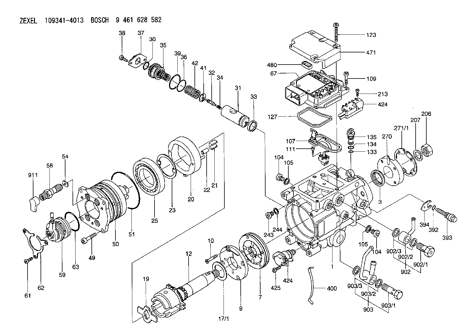
| 1. | [1] | 149004-1020 | PUMP HOUSING |
| 3. | [1] | 149351-0201 | PACKING RING |
| 7. | [1] | 149050-0220 | SUPPLY PUMP |
| 9. | [1] | 149055-0000 | SUPPORT RING |
| 10. | [4] | 149330-2000 | TORX SCREW |
| 12. | [1] | 149100-0520 | DRIVE SHAFT |
| 17/1. | [1] | 149110-0000 | SHIM 1460125040 |
| 17/1B. | [1] | 149110-0100 | SHIM 1460125041 |
| 17/1C. | [1] | 149110-0200 | SHIM |
| 17/1D. | [1] | 149110-0300 | SHIM 1460125043 |
| 17/1E. | [1] | 149110-0400 | SHIM 1460125044 |
| 17/1F. | [1] | 149110-0500 | SHIM 1460125045 |
| 17/1G. | [1] | 149110-0600 | SHIM 1460125046 |
| 17/1H. | [1] | 149110-0700 | SHIM 1460125047 |
| 17/1I. | [1] | 149110-0800 | SHIM 1460125048 |
| 17/1J. | [1] | 149110-0900 | SHIM 1460125049 |
| 17/1K. | [1] | 149110-1000 | SHIM 1460125050 |
| 17B/1. | [1] | 149110-1200 | SHIM |
| 17B/1B. | [1] | 149110-1300 | SHIM |
| 17B/1C. | [1] | 149110-1400 | SHIM |
| 17B/1D. | [1] | 149110-1500 | SHIM |
| 17B/1E. | [1] | 149110-1600 | SHIM |
| 17B/1F. | [1] | 149110-1700 | SHIM |
| 17B/1G. | [1] | 149110-1800 | SHIM |
| 17B/1H. | [1] | 149110-1900 | SHIM |
| 17B/1I. | [1] | 149110-2000 | SHIM |
| 17B/1J. | [1] | 149110-2100 | SHIM |
| 17B/1K. | [1] | 149110-2200 | SHIM |
| 19. | [1] | 149111-0000 | DRIVER DISC |
| 20. | [1] | 149120-0020 | CAM RING |
| 21. | [2] | 149112-0200 | ROLLER SHOE |
| 22. | [2] | 149113-0000 | ROLLER |
| 23. | [1] | 149111-0100 | PLATE |
| 25. | [1] | 149114-0000 | BEARING PLATE |
| 30. | [1] | 149350-1500 | O-RING |
| 31. | [1] | 149150-0021 | TIMING-DEVICE PISTON |
| 32. | [1] | 149160-0000 | (CONTROL SPOOL) |
| 33. | [1] | 149161-0100 | PISTON RING |
| 34. | [1] | 149162-0000 | COILED SPRING |
| 35. | [1] | 149170-0022 | HYDRAULIC STOPPER |
| 36. | [1] | 149350-1600 | O-RING |
| 37. | [1] | 149180-0101 | CLOSING COVER |
| 38. | [2] | 149330-1800 | TORX BOLT |
| 39. | [1] | 149350-1700 | SEAL RING |
| 41. | [1] | 149163-0100 | PLATE |
| 42. | [1] | 149164-0000 | COILED SPRING |
| 49. | [4] | 149330-1900 | TORX BOLT |
| 50. | [1] | 149200-1020 | HYDRAULIC HEAD |
| 51. | [3] | 149350-2000 | O-RING |
| 54. | [4] | 149313-2700 | GASKET |
| 58. | [4] | 149300-0023 | PRESSURE-CONTROL VALVE |
| 59. | [1] | 479763-4920 | MAGNET |
| 61. | [3] | 149330-2300 | TORX BOLT |
| 62. | [1] | 149436-0000 | PLATE |
| 63. | [1] | 149350-1900 | O-RING |
| 67. | [1] | 149404-0220 | PSG |
| 104. | [2] | 149330-2400 | HEX-SOCKET-HEAD CAP SCREW |
| 104. | [2] | 149330-2400 | HEX-SOCKET-HEAD CAP SCREW |
| 105. | [2] | 149443-0200 | GASKET |
| 105. | [2] | 149443-0200 | GASKET |
| 107. | [1] | 149403-0020 | SENSOR |
| 109. | [3] | 149330-1600 | TORX BOLT |
| 111. | [2] | 149330-0501 | TORX SCREW |
| 123. | [5] | 149330-1700 | TORX BOLT |
| 127. | [1] | 149350-2800 | SEAL RING |
| 133. | [1] | 149350-2900 | O-RING |
| 134. | [1] | 149350-3000 | O-RING |
| 135. | [1] | 149060-0020 | CONTROL VALVE |
| 206. | [1] | 149330-1200 | UNION NUT |
| 207. | [1] | 149412-0000 | PLAIN WASHER |
| 213. | [2] | 149330-0400 | TORX SCREW |
| 243. | [1] | 149330-2400 | HEX-SOCKET-HEAD CAP SCREW |
| 244. | [1] | 149443-0200 | GASKET |
| 270. | [1] | 149411-2600 | COUPLING PLATE |
| 271/1. | [1] | 149411-1300 | SHIM 1460125106 |
| 271/1B. | [1] | 149411-1400 | SHIM 1460125107 |
| 271/1C. | [1] | 149411-1500 | SHIM 1460125108 |
| 271/1D. | [1] | 149411-1600 | SHIM 1460125109 |
| 271/1E. | [1] | 149411-1700 | SHIM 1460125110 |
| 271/1F. | [1] | 149411-1800 | SHIM 1460125111 |
| 271/1G. | [1] | 149411-1900 | SHIM 1460125112 |
| 271/1H. | [1] | 149411-2000 | SHIM 1460125113 |
| 271/1I. | [1] | 149411-2100 | SHIM 1460125114 |
| 271/1J. | [1] | 149411-2200 | SHIM 1460125115 |
| 271/1K. | [1] | 149411-2300 | SHIM 1460125116 |
| 271B/1. | [1] | 149411-4000 | SHIM |
| 271B/1B. | [1] | 149411-4100 | SHIM |
| 271B/1C. | [1] | 149411-4200 | SHIM |
| 271B/1D. | [1] | 149411-4300 | SHIM |
| 271B/1E. | [1] | 149411-4400 | SHIM |
| 271B/1F. | [1] | 149411-4500 | SHIM |
| 271B/1G. | [1] | 149411-4600 | SHIM |
| 271B/1H. | [1] | 149411-4700 | SHIM |
| 271B/1I. | [1] | 149411-4800 | SHIM |
| 271B/1J. | [1] | 149411-4900 | SHIM |
| 271B/1K. | [1] | 149411-5000 | SHIM |
| 392. | [1] | 149350-3100 | O-RING |
| 393. | [1] | 149419-0100 | BLEEDER SCREW |
| 394. | [1] | 149420-0000 | INTERMEDIATE PLATE |
| 394B. | [1] | 149420-0001 | INTERMEDIATE PLATE |
| 400. | [1] | 149460-1300 | CABLE CRAMP |
| 424. | [1] | 149402-0020 | TIMING CONTROL VALVE |
| 424. | [1] | 149402-0020 | TIMING CONTROL VALVE |
| 425. | [2] | 149330-2200 | TORX BOLT |
| 471. | [1] | 149410-0000 | COVER |
| 480. | [1] | 149350-3200 | SEAL RING |
| 902. | [1] | 149433-0220 | OUTLET PIPE ASSY |
| 902/1. | [1] | 149070-0021 | OVER FLOW VALVE |
| 902/2. | [1] | 146669-4420 | INLET UNION |
| 902/3. | [2] | 149350-2700 | FLAT SEAL RING |
| 903. | [1] | 149428-0520 | INLET PIPE |
| 903/1. | [1] | 149330-0000 | EYE BOLT |
| 903/2. | [1] | 149425-0020 | INLET UNION |
| 903/3. | [2] | 149350-2600 | FLAT SEAL RING |
| 911. | [4] | 149460-0600 | CAP |
Include in #2:
109341-4013
as INJECTION-PUMP ASSEMBLY
Cross reference number
Zexel num
Bosch num
Firm num
Name
Information:
1. The customer must be asked questions to determine whether his complaint is valid, or whether his diagnosis of the actual problem is correct.Some of the questions that must be asked are as follows:a. What components are vibrating?b. In what speed range does this vibration become excessive?c. Does clutch operation affect the vibration?d. What is the history of the problem?2. Run the engine through the idle speed range and note all vibrating components. Look for any loose or broken mounts, brackets, and fasteners. Repair and tighten any fixtures.3. Check idle speed range with clutch disengaged. If vibrations subside, there is a balance problem with the clutch disc. The clutch disc must be repaired or replaced.4. Further analysis requires the use of a vibration instrument. Any instrument which can accurately measure the displacement of the vibration (usually in mils-inch/1000) and the frequency (cycles per minute) will be sufficient. A vibration instrument such as the IRD Mechanalysis Model 320 or an equivalent instrument can be used to analyze vibration.5. Measure vibration of cab components which have the objectionable vibration.Run engine slowly through the speed range and measure vibration with the instrument filter out. When peak amplitudes are found, run the engine at the speeds they occur and with the instrument filter IN, find the frequency of the vibration.If the frequency of vibration is 1/2 times of engine rpm (1/2 order), the vibration is caused by a cylinder misfiring. This must be corrected before further vibration analysis is made.If the frequency of vibration is 3 times engine rpm, no corrective action can be taken on the engine because this is the firing frequency of the 3306 engine. The problem is in the cab or chassis resonance.If frequency is some order other than 1/2 or 3rd, then further measurements must be made on the engine.6. Measurements taken on the engine must be made perpendicular to the crankshaft at the front and rear of the engine in vertical and horizontal directions.7. Records all vibrations over 4.0 mils and the engine rpm at whcih it occurs (100 rpm intervals are sufficient) with instrument filter out. Note any sudden increase and decrease in amplitudes. These occur in resonant speed ranges.If no amplitudes exceed 4.0 mils, the engine is within Caterpillar Specs.If amplitudes exceed 4.0 mils, the vibrations must be measured with the instrument filter "IN" to obtain the frequency of the vibrations.8. Run the engine at high idle. With the instrument filter IN, check the frequency range and record any amplitudes over 4.0 mils and the corresponding frequency. Analysis of vibrations for the possible causes is done by identifying the frequency of the vibration and where on the engine it is the greatest magnitude.