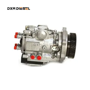
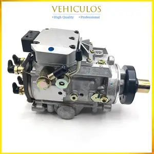
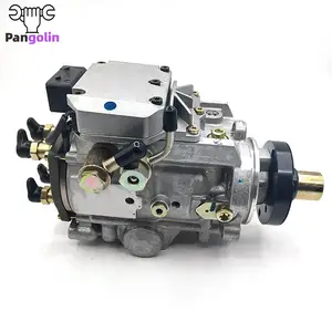
Information injection-pump assembly
BOSCH
0 470 504 033
0470504033
ZEXEL
109341-2072
1093412072
NISSAN
16700VK50A
16700vk50a

Rating:
Compare Prices: .
As an associate, we earn commssions on qualifying purchases through the links below

Aftermarket Bosch 0470504033 16700-VK500 Fuel Injection Pump for Nissan NP300 Navara 2004-2015
100% Apollo part number:0470504033 16700-VK500 || application: for Nissan NP300 Navara 2004-2015
100% Apollo part number:0470504033 16700-VK500 || application: for Nissan NP300 Navara 2004-2015

Original New Fuel Pump Compatible For Nissan NP300 NAVRA 2.5DCi 0470504033 Engine Car Replacement Parts
ZKZQPOCU The standardized design and interface make the installation and disassembly of the fuel pump on the vehicle relatively simple and easy to replace. || Using excellent materials and advanced manufacturing technology, it has a long service life and good reliability, and reduces the occurrence of faulty anchors. || Accurately control the injection quantity to make the fuel fully burn in the cylinder, effectively improve the fuel economy and reduce the use cost of the vehicle. || Whether the vehicle is climbing, accelerating, decelerating or idling, it can respond quickly, provide stable fuel supply and ensure the consistency of engine power output. || Original New Fuel Pump Compatible For Nissan NP300 NAVRA 2.5DCi 0470504033 Engine Car Replacement Parts
ZKZQPOCU The standardized design and interface make the installation and disassembly of the fuel pump on the vehicle relatively simple and easy to replace. || Using excellent materials and advanced manufacturing technology, it has a long service life and good reliability, and reduces the occurrence of faulty anchors. || Accurately control the injection quantity to make the fuel fully burn in the cylinder, effectively improve the fuel economy and reduce the use cost of the vehicle. || Whether the vehicle is climbing, accelerating, decelerating or idling, it can respond quickly, provide stable fuel supply and ensure the consistency of engine power output. || Original New Fuel Pump Compatible For Nissan NP300 NAVRA 2.5DCi 0470504033 Engine Car Replacement Parts

Fuel Pump 0470504033, Compatible With Nissan NP300 2.5DCi, OEM Precision Fitment, High-Efficiency Fuel Delivery
Adfghjk [Precise Fit] Fuel pump (model 0470504033) is compatible with Nissan NP300 2.5DCi design, seamlessly matches the original fuel line connector, 10-minute quick installation. || [Efficient Delivery] Reinforced alloy core and high-pressure fuel technology increase fuel flow by 20%, optimizing diesel combustion efficiency. || [Factory Certified] ISO 9001 certified, fully compatible with factory ECU and sensors, eliminating fuel leaks or fault codes. || [Industrial Grade Durability] Carbon steel filter + anti-rust coating, resistant to high load conditions, with a lifespan of up to 150,000 kilometers. || [Ready-to-Use] Integrated oil pump, sealing components and sensors, no need to debug, save 50% maintenance time.
Adfghjk [Precise Fit] Fuel pump (model 0470504033) is compatible with Nissan NP300 2.5DCi design, seamlessly matches the original fuel line connector, 10-minute quick installation. || [Efficient Delivery] Reinforced alloy core and high-pressure fuel technology increase fuel flow by 20%, optimizing diesel combustion efficiency. || [Factory Certified] ISO 9001 certified, fully compatible with factory ECU and sensors, eliminating fuel leaks or fault codes. || [Industrial Grade Durability] Carbon steel filter + anti-rust coating, resistant to high load conditions, with a lifespan of up to 150,000 kilometers. || [Ready-to-Use] Integrated oil pump, sealing components and sensors, no need to debug, save 50% maintenance time.
You can express buy:
USD 1269.56
19-05-2025
19-05-2025
VP44 Diesel Engine Pump Common Rail Fuel · Pump 0470504033 Rebuild
USD 5148.22
19-05-2025
19-05-2025
Brand New Original Engine Fuel Pump For Nissan NP300 NAVRA 2.5DCi 0470504033 High Pressure Fuel Pump Accessories Parts
USD 4265.79
29-04-2025
29-04-2025
1pc Fuel Pump 0470504033 For Nissan NP300 NAVRA 2.5DCi
Components :
| 0. | INJECTION-PUMP ASSEMBLY | 109341-2072 |
| 1. | _ | |
| 2. | FUEL INJECTION PUMP | 109241-2072 |
| 3. | NUMBER PLATE | |
| 4. | _ | |
| 5. | CAPSULE | |
| 6. | ADJUSTING DEVICE | |
| 7. | NOZZLE AND HOLDER ASSY | 105118-8280 |
| 8. | Nozzle and Holder | 16600VK500 |
| 9. | Open Pre:MPa(Kqf/cm2) | 19.0{194}/37.5{382} |
| 10. | NOZZLE-HOLDER | |
| 11. | NOZZLE |
Scheme ###:
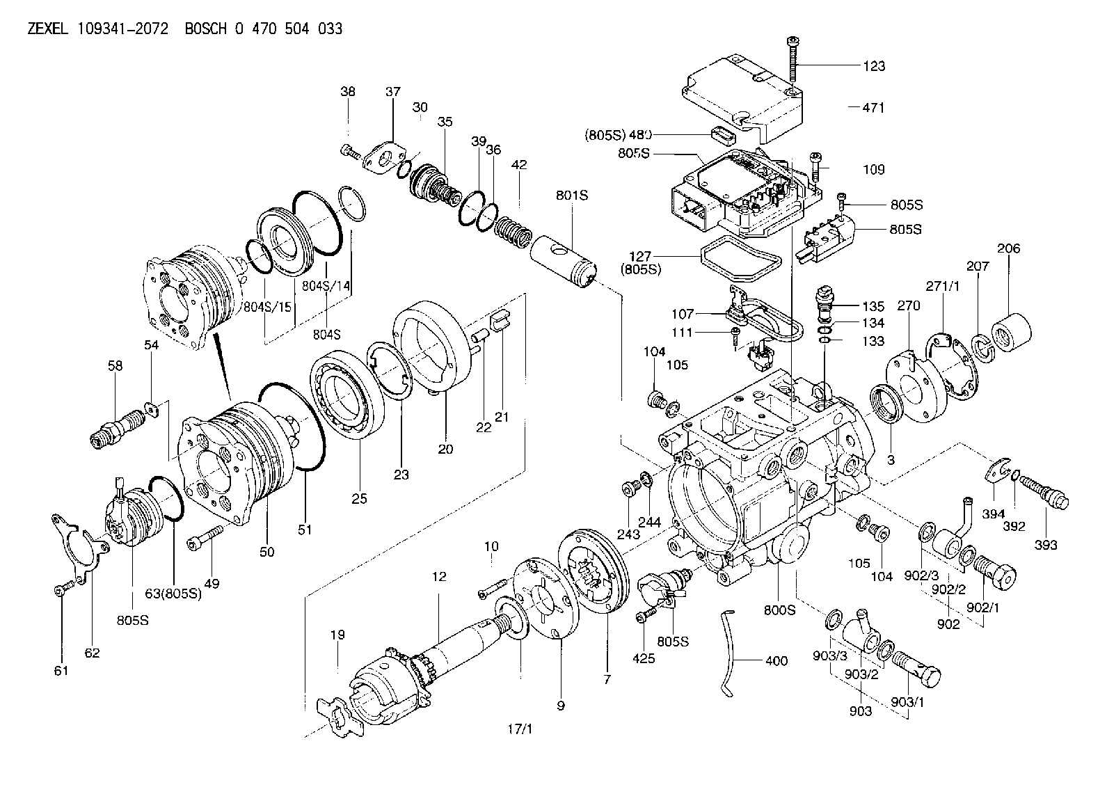
| 3. | [1] | 149351-0201 | PACKING RING |
| 7. | [1] | 149050-0220 | SUPPLY PUMP |
| 9. | [1] | 149055-0000 | SUPPORT RING |
| 10. | [4] | 149330-2000 | TORX SCREW |
| 12. | [1] | 149100-0520 | DRIVE SHAFT |
| 17/1. | [1] | 149110-0000 | SHIM D42.5627.1T2.2 |
| 17/1B. | [1] | 149110-0100 | SHIM D42.5&27.1T2.3 |
| 17/1C. | [1] | 149110-0200 | SHIM D42.5&27.1T2.4 |
| 17/1D. | [1] | 149110-0300 | SHIM D42.5&27.1T2.5 |
| 17/1E. | [1] | 149110-0400 | SHIM D42.5&27.1T2.6 |
| 17/1F. | [1] | 149110-0500 | SHIM D42.5&27.1T2.7 |
| 17/1G. | [1] | 149110-0600 | SHIM D42.5&27.1T2.8 |
| 17/1H. | [1] | 149110-0700 | SHIM D42.5&27.1T2.9 |
| 17/1I. | [1] | 149110-0800 | SHIM D42.5&27.1T3.0 |
| 17/1J. | [1] | 149110-0900 | SHIM D42.5&27.1T3.1 |
| 17/1K. | [1] | 149110-1000 | SHIM D42.5&27.1T3.2 |
| 17B/1. | [1] | 149110-1200 | SHIM D42.5&27.1T2.2 |
| 17B/1B. | [1] | 149110-1300 | SHIM D42.5&27.1T2.3 |
| 17B/1C. | [1] | 149110-1400 | SHIM D42.5&27.1T2.4 |
| 17B/1D. | [1] | 149110-1500 | SHIM D42.5&27.1T2.5 |
| 17B/1E. | [1] | 149110-1600 | SHIM D42.5&27.1T2.6 |
| 17B/1F. | [1] | 149110-1700 | SHIM D42.5&27.1T2.7 |
| 17B/1G. | [1] | 149110-1800 | SHIM D42.5&27.1T2.8 |
| 17B/1H. | [1] | 149110-1900 | SHIM D42.5&27.1T2.9 |
| 17B/1I. | [1] | 149110-2000 | SHIM D42.5&27.1T3.0 |
| 17B/1J. | [1] | 149110-2100 | SHIM D42.5&27.1T3.1 |
| 17B/1K. | [1] | 149110-2200 | SHIM D42.5&27.1T3.2 |
| 19. | [1] | 149111-0000 | DRIVER DISC |
| 20. | [1] | 149120-0120 | CAM RING |
| 21. | [2] | 149112-0200 | ROLLER SHOE |
| 22. | [2] | 149113-0300 | ROLLER |
| 23. | [1] | 149111-0100 | PLATE |
| 25. | [1] | 149114-0000 | BEARING PLATE |
| 30. | [1] | 149350-3300 | O-RING |
| 35. | [1] | 149170-0022 | HYDRAULIC STOPPER |
| 36. | [1] | 149350-3400 | O-RING |
| 37. | [1] | 149180-0300 | CLOSING COVER |
| 38. | [2] | 149330-2900 | TORX BOLT |
| 39. | [1] | 149350-1700 | SEAL RING |
| 42. | [1] | 149164-0000 | COILED SPRING |
| 49. | [4] | 149330-3900 | TORX BOLT |
| 50. | [1] | 149200-0723 | HYDRAULIC HEAD |
| 51. | [3] | 149350-2000 | O-RING |
| 54. | [4] | 149313-2700 | GASKET |
| 58. | [4] | 149305-0020 | RESTRICTION |
| 61. | [3] | 149330-3400 | TORX BOLT |
| 62. | [1] | 149436-0100 | PLATE |
| 63. | [1] | 149350-1900 | O-RING |
| 104. | [2] | 149330-3500 | HEX-SOCKET-HEAD CAP SCREW |
| 104. | [2] | 149330-3500 | HEX-SOCKET-HEAD CAP SCREW |
| 105. | [2] | 149443-0200 | GASKET |
| 105. | [2] | 149443-0200 | GASKET |
| 107. | [1] | 149403-0320 | SENSOR |
| 107B. | [1] | 149403-0520 | SENSOR |
| 109. | [3] | 149330-1600 | TORX BOLT |
| 111. | [2] | 149330-0501 | TORX SCREW |
| 123. | [5] | 149330-3900 | TORX BOLT |
| 127. | [1] | 149350-2800 | SEAL RING |
| 133. | [1] | 149350-3500 | O-RING |
| 134. | [1] | 149350-3600 | O-RING |
| 135. | [1] | 149060-0520 | CONTROL VALVE |
| 206. | [1] | 149413-0200 | UNION NUT |
| 207. | [1] | 149412-0100 | PLAIN WASHER |
| 243. | [1] | 149330-3500 | HEX-SOCKET-HEAD CAP SCREW |
| 244. | [1] | 149443-0200 | GASKET |
| 270. | [1] | 149411-2500 | COUPLING PLATE |
| 271/1. | [1] | 149411-0200 | SHIM T0.5 |
| 271/1B. | [1] | 149411-0300 | SHIM T0.6 |
| 271/1C. | [1] | 149411-0400 | SHIM T0.7 |
| 271/1D. | [1] | 149411-0500 | SHIM T0.8 |
| 271/1E. | [1] | 149411-0600 | SHIM T0.9 |
| 271/1F. | [1] | 149411-0700 | SHIM T1.0 |
| 271/1G. | [1] | 149411-0800 | SHIM T1.1 |
| 271/1H. | [1] | 149411-0900 | SHIM T1.2 |
| 271/1I. | [1] | 149411-1000 | SHIM T1.3 |
| 271/1J. | [1] | 149411-1100 | SHIM T1.4 |
| 271/1K. | [1] | 149411-1200 | SHIM T1.5 |
| 271B/1. | [1] | 149411-2800 | SHIM T0.5 |
| 271B/1B. | [1] | 149411-2900 | SHIM T0.6 |
| 271B/1C. | [1] | 149411-3000 | SHIM T0.7 |
| 271B/1D. | [1] | 149411-3100 | SHIM T0.8 |
| 271B/1E. | [1] | 149411-3200 | SHIM T0.9 |
| 271B/1F. | [1] | 149411-3300 | SHIM T1.0 |
| 271B/1G. | [1] | 149411-3400 | SHIM T1.1 |
| 271B/1H. | [1] | 149411-3500 | SHIM T1.2 |
| 271B/1I. | [1] | 149411-3600 | SHIM T1.3 |
| 271B/1J. | [1] | 149411-3700 | SHIM T1.4 |
| 271B/1K. | [1] | 149411-3800 | SHIM T1.5 |
| 392. | [1] | 149350-3700 | O-RING |
| 393. | [1] | 149419-0600 | BLEEDER SCREW |
| 394. | [1] | 149420-0001 | INTERMEDIATE PLATE |
| 400. | [1] | 149460-1300 | CABLE CRAMP |
| 425. | [2] | 149330-3300 | TORX BOLT |
| 471. | [1] | 149410-0000 | COVER |
| 480. | [1] | 149350-3800 | SEAL RING |
| 800S. | [1] | 149480-0220 | SERVICE PARTS GROUP |
| 801S. | [1] | 149481-0420 | PARTS SET |
| 804S. | [1] | 149483-0020 | PARTS SET |
| 804S/14. | [1] | 149350-1800 | O-RING |
| 804S/15. | [1] | 149350-1900 | O-RING |
| 805S. | [1] | 149482-0220 | PARTS SET |
| 805S. | [1] | 149482-0220 | PARTS SET |
| 805S. | [1] | 149482-0220 | PARTS SET |
| 805S. | [1] | 149482-0220 | PARTS SET |
| 805S. | [1] | 149482-0220 | PARTS SET |
| 805S. | [1] | 149482-0220 | PARTS SET |
| 805S. | [1] | 149482-0220 | PARTS SET |
| 805S. | [1] | 149482-0220 | PARTS SET |
| 902. | [1] | 149433-0220 | OUTLET PIPE ASSY |
| 902/1. | [1] | 149070-0120 | OVER FLOW VALVE |
| 902/2. | [1] | 146669-4420 | INLET UNION |
| 902/3. | [2] | 149350-2700 | FLAT SEAL RING |
| 903. | [1] | 149428-0220 | INLET PIPE |
| 903/1. | [1] | 149330-0000 | EYE BOLT |
| 903/2. | [1] | 146669-4320 | INLET UNION |
| 903/3. | [2] | 149350-2600 | FLAT SEAL RING |
Include in #2:
109341-2072
as INJECTION-PUMP ASSEMBLY
Cross reference number
Zexel num
Bosch num
Firm num
Name
0 470 504 033
16700VK50A NISSAN
INJECTION-PUMP ASSEMBLY
YD2ETI A * K 13CJ INJECTION PUMP ASSY VP44 VP44
YD2ETI A * K 13CJ INJECTION PUMP ASSY VP44 VP44
Information:
Recommended Procedure1. Air in Fuel System ... With air in the fuel system, the engine will normally be difficult to start, run rough, and release a large amount of white smoke. If the engine will not start, loosen a fuel injection line nut at the cylinder head. With the governor lever in the shutoff position, operate the fuel priming pump until the flow of fuel from the loosened fuel injection line is free of air. Tighten the fuel line nut. Fasten the priming pump and start the engine. If the engine still does not run smooth or releases a large amount of white smoke, loosen the fuel line nuts one at a time at the cylinder head until the fuel that comes out is free of air. Tighten the fuel line nuts. If the air can not be removed in this way, put 5 psi (35 kPa) of air pressure to the fuel tank.
Do not use more than 8 psi (55 kPa) of air pressure in the fuel tank or damage to the tank may result.
Check for leaks at the connections between the fuel tank and the fuel transfer pump. If leaks are found, tighten the connections or replace the lines. If there are no visual leaks, remove the fuel supply line from the tank and connect it to an outside fuel supply. If this corrects the problem, the suction line (standpipe) inside the fuel tank has a leak.2. Valve Adjustment Not Correct ... Check and make necessary adjustments as per Testing and Adjusting section of this Service Manual. Intake valve clearance is .015 in. (0.38 mm) and exhaust valve clearance is .025 in. (0.64 mm). Also check for a bent or broken push rod.3. Fuel Injection Timing Not Correct ... Check and make necessary adjustments as per Testing and Adjusting section of this Service Manual.4. Automatic Timing Advance Does Not Operate Correctly ... Check with engine warm. Use the 1P3500 Timing Light Group. Special Instruction Form No. SMHS6964 gives the test procedure. If the timing light is not available, make rapid "acceleration" (increase in speed) from low idle to high idle. Engine must have smooth acceleration. A timing advance that does not operate correctly can cause delays of the engine acceleration at some rpm before high idle, or possibly cause the engine to run rough and have exhaust noise (backfire) during acceleration. This condition is difficult to find if engine acceleration is slow or at a constant engine rpm.5. Bad Fuel Nozzle(s) ... Find a bad nozzle by running engine at the rpm where it runs rough. Loosen the fuel line nut at the cylinder head enough to stop fuel supply to that cylinder. Each cylinder must be checked this way. If a cylinder is found where loosening of the nut makes no difference in the rough running, test the nozzle for that cylinder. To test a nozzle, remove the nozzle from the engine and test as per Testing and Adjusting section of this Service Manual.6.