Information injection-pump assembly
BOSCH
0 470 504 012
0470504012
ZEXEL
109341-2054
1093412054
NISSAN
167005M321
167005m321
Rating:
Components :
| 0. | INJECTION-PUMP ASSEMBLY | 109341-2054 |
| 1. | _ | |
| 2. | FUEL INJECTION PUMP | 109241-2054 |
| 3. | NUMBER PLATE | |
| 4. | _ | |
| 5. | CAPSULE | |
| 6. | ADJUSTING DEVICE | |
| 7. | NOZZLE AND HOLDER ASSY | 105118-8180 |
| 8. | Nozzle and Holder | |
| 9. | Open Pre:MPa(Kqf/cm2) | 21.0{214}/39.5{403} |
| 10. | NOZZLE-HOLDER | |
| 11. | NOZZLE |
Scheme ###:
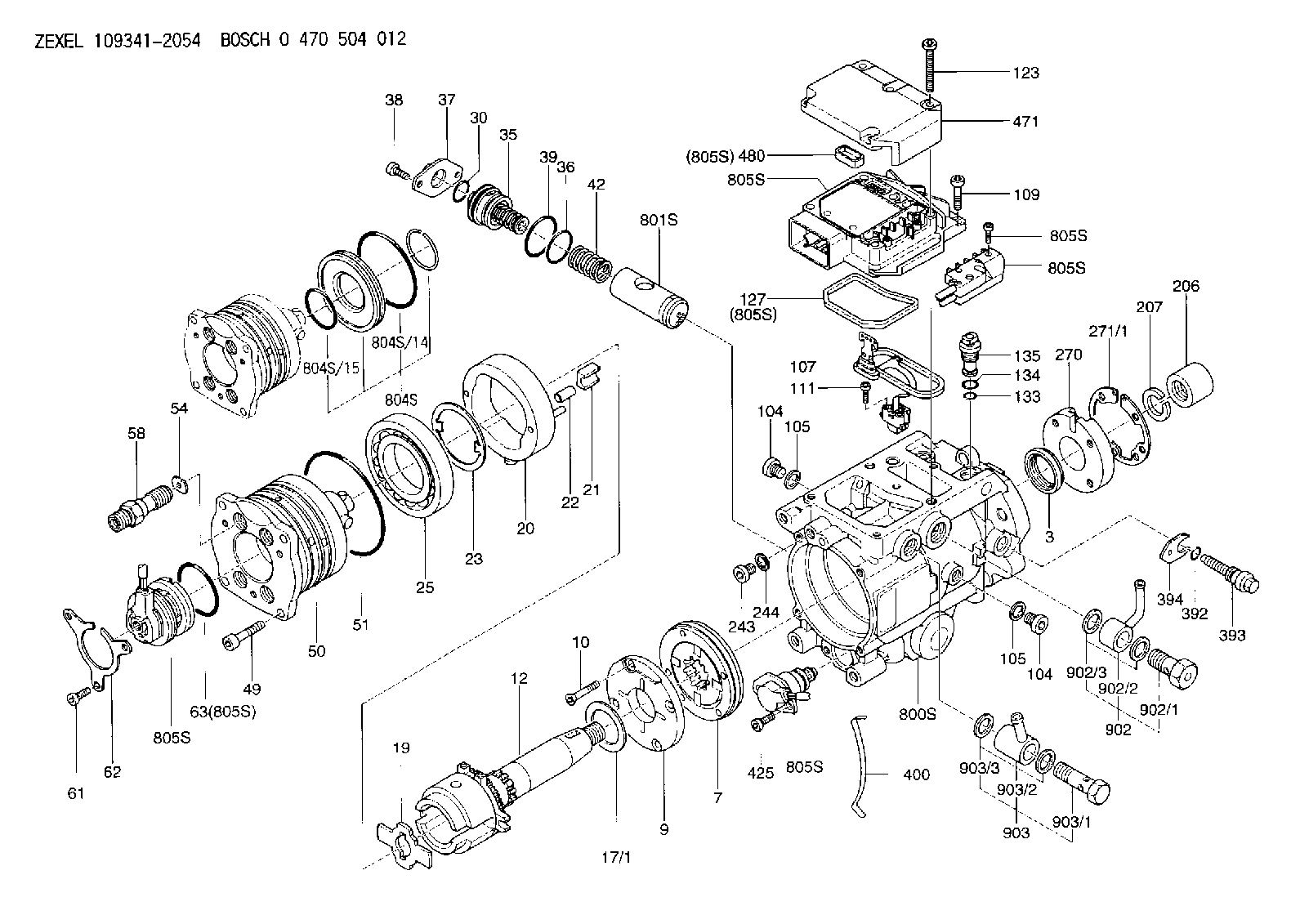
| 3. | [1] | 149351-0100 | PACKING RING |
| 3B. | [1] | 149351-0201 | PACKING RING |
| 7. | [1] | 149050-0220 | SUPPLY PUMP |
| 9. | [1] | 149055-0000 | SUPPORT RING |
| 10. | [4] | 149330-2000 | TORX SCREW |
| 12. | [1] | 149100-0520 | DRIVE SHAFT |
| 17/1. | [1] | 149110-0000 | SHIM D42.5627.1T2.2 |
| 17/1B. | [1] | 149110-0100 | SHIM D42.5&27.1T2.3 |
| 17/1C. | [1] | 149110-0200 | SHIM D42.5&27.1T2.4 |
| 17/1D. | [1] | 149110-0300 | SHIM D42.5&27.1T2.5 |
| 17/1E. | [1] | 149110-0400 | SHIM D42.5&27.1T2.6 |
| 17/1F. | [1] | 149110-0500 | SHIM D42.5&27.1T2.7 |
| 17/1G. | [1] | 149110-0600 | SHIM D42.5&27.1T2.8 |
| 17/1H. | [1] | 149110-0700 | SHIM D42.5&27.1T2.9 |
| 17/1I. | [1] | 149110-0800 | SHIM D42.5&27.1T3.0 |
| 17/1J. | [1] | 149110-0900 | SHIM D42.5&27.1T3.1 |
| 17/1K. | [1] | 149110-1000 | SHIM D42.5&27.1T3.2 |
| 17B/1. | [1] | 149110-1200 | SHIM D42.5&27.1T2.2 |
| 17B/1B. | [1] | 149110-1300 | SHIM D42.5&27.1T2.3 |
| 17B/1C. | [1] | 149110-1400 | SHIM D42.5&27.1T2.4 |
| 17B/1D. | [1] | 149110-1500 | SHIM D42.5&27.1T2.5 |
| 17B/1E. | [1] | 149110-1600 | SHIM D42.5&27.1T2.6 |
| 17B/1F. | [1] | 149110-1700 | SHIM D42.5&27.1T2.7 |
| 17B/1G. | [1] | 149110-1800 | SHIM D42.5&27.1T2.8 |
| 17B/1H. | [1] | 149110-1900 | SHIM D42.5&27.1T2.9 |
| 17B/1I. | [1] | 149110-2000 | SHIM D42.5&27.1T3.0 |
| 17B/1J. | [1] | 149110-2100 | SHIM D42.5&27.1T3.1 |
| 17B/1K. | [1] | 149110-2200 | SHIM D42.5&27.1T3.2 |
| 19. | [1] | 149111-0000 | DRIVER DISC |
| 20. | [1] | 149120-1120 | CAM RING |
| 21. | [2] | 149112-0200 | ROLLER SHOE |
| 22. | [2] | 149113-0200 | ROLLER |
| 22B. | [2] | 149113-0300 | ROLLER |
| 23. | [1] | 149111-0100 | PLATE |
| 25. | [1] | 149114-0000 | BEARING PLATE |
| 30. | [1] | 149350-3300 | O-RING |
| 35. | [1] | 149170-0022 | HYDRAULIC STOPPER |
| 36. | [1] | 149350-3400 | O-RING |
| 37. | [1] | 149180-0300 | CLOSING COVER |
| 38. | [2] | 149330-2900 | TORX BOLT |
| 39. | [1] | 149350-1700 | SEAL RING |
| 42. | [1] | 149164-0000 | COILED SPRING |
| 49. | [4] | 149330-3900 | TORX BOLT |
| 50. | [1] | 149200-0723 | HYDRAULIC HEAD |
| 51. | [3] | 149350-2000 | O-RING |
| 54. | [4] | 149313-2700 | GASKET |
| 58. | [4] | 149300-1120 | PRESSURE-CONTROL VALVE |
| 61. | [3] | 149330-3400 | TORX BOLT |
| 62. | [1] | 149436-0100 | PLATE |
| 63. | [1] | 149350-1900 | O-RING |
| 104. | [2] | 149330-3500 | HEX-SOCKET-HEAD CAP SCREW |
| 104. | [2] | 149330-3500 | HEX-SOCKET-HEAD CAP SCREW |
| 105. | [2] | 149443-0200 | GASKET |
| 105. | [2] | 149443-0200 | GASKET |
| 107. | [1] | 149403-0320 | SENSOR |
| 107B. | [1] | 149403-0520 | SENSOR |
| 109. | [3] | 149330-1600 | TORX BOLT |
| 111. | [2] | 149330-0501 | TORX SCREW |
| 123. | [5] | 149330-3900 | TORX BOLT |
| 127. | [1] | 149350-2800 | SEAL RING |
| 133. | [1] | 149350-3500 | O-RING |
| 134. | [1] | 149350-3600 | O-RING |
| 135. | [1] | 149060-0520 | CONTROL VALVE |
| 206. | [1] | 149413-0200 | UNION NUT |
| 207. | [1] | 149412-0100 | PLAIN WASHER |
| 243. | [1] | 149330-3500 | HEX-SOCKET-HEAD CAP SCREW |
| 244. | [1] | 149443-0200 | GASKET |
| 270. | [1] | 149411-2500 | COUPLING PLATE |
| 271/1. | [1] | 149411-0200 | SHIM T0.5 |
| 271/1B. | [1] | 149411-0300 | SHIM T0.6 |
| 271/1C. | [1] | 149411-0400 | SHIM T0.7 |
| 271/1D. | [1] | 149411-0500 | SHIM T0.8 |
| 271/1E. | [1] | 149411-0600 | SHIM T0.9 |
| 271/1F. | [1] | 149411-0700 | SHIM T1.0 |
| 271/1G. | [1] | 149411-0800 | SHIM T1.1 |
| 271/1H. | [1] | 149411-0900 | SHIM T1.2 |
| 271/1I. | [1] | 149411-1000 | SHIM T1.3 |
| 271/1J. | [1] | 149411-1100 | SHIM T1.4 |
| 271/1K. | [1] | 149411-1200 | SHIM T1.5 |
| 271B/1. | [1] | 149411-2800 | SHIM T0.5 |
| 271B/1B. | [1] | 149411-2900 | SHIM T0.6 |
| 271B/1C. | [1] | 149411-3000 | SHIM T0.7 |
| 271B/1D. | [1] | 149411-3100 | SHIM T0.8 |
| 271B/1E. | [1] | 149411-3200 | SHIM T0.9 |
| 271B/1F. | [1] | 149411-3300 | SHIM T1.0 |
| 271B/1G. | [1] | 149411-3400 | SHIM T1.1 |
| 271B/1H. | [1] | 149411-3500 | SHIM T1.2 |
| 271B/1I. | [1] | 149411-3600 | SHIM T1.3 |
| 271B/1J. | [1] | 149411-3700 | SHIM T1.4 |
| 271B/1K. | [1] | 149411-3800 | SHIM T1.5 |
| 392. | [1] | 149350-3700 | O-RING |
| 393. | [1] | 149419-0600 | BLEEDER SCREW |
| 394. | [1] | 149420-0001 | INTERMEDIATE PLATE |
| 400. | [1] | 149460-1300 | CABLE CRAMP |
| 425. | [2] | 149330-3300 | TORX BOLT |
| 471. | [1] | 149410-0000 | COVER |
| 480. | [1] | 149350-3800 | SEAL RING |
| 800S. | [1] | 149480-0220 | SERVICE PARTS GROUP |
| 801S. | [1] | 149481-0320 | PARTS SET |
| 804S. | [1] | 149483-0020 | PARTS SET |
| 804S/14. | [1] | 149350-1800 | O-RING |
| 804S/15. | [1] | 149350-1900 | O-RING |
| 805S. | [1] | 149482-0020 | PARTS SET |
| 805S. | [1] | 149482-0020 | PARTS SET |
| 805S. | [1] | 149482-0020 | PARTS SET |
| 805S. | [1] | 149482-0020 | PARTS SET |
| 805S. | [1] | 149482-0020 | PARTS SET |
| 805S. | [1] | 149482-0020 | PARTS SET |
| 805S. | [1] | 149482-0020 | PARTS SET |
| 805S. | [1] | 149482-0020 | PARTS SET |
| 902. | [1] | 149433-0220 | OUTLET PIPE ASSY |
| 902/1. | [1] | 149070-0120 | OVER FLOW VALVE |
| 902/2. | [1] | 146669-4420 | INLET UNION |
| 902/3. | [2] | 149350-2700 | FLAT SEAL RING |
| 903. | [1] | 149428-0220 | INLET PIPE |
| 903/1. | [1] | 149330-0000 | EYE BOLT |
| 903/2. | [1] | 146669-4320 | INLET UNION |
| 903/3. | [2] | 149350-2600 | FLAT SEAL RING |
Include in #2:
109341-2054
as INJECTION-PUMP ASSEMBLY
Cross reference number
Zexel num
Bosch num
Firm num
Name
109341-2054
0 470 504 012
167005M321 NISSAN
INJECTION-PUMP ASSEMBLY
YD1 B K 13CJ VP44 VP44
YD1 B K 13CJ VP44 VP44
109341-2054
0 470 504 012
A67005M321 NISSAN
INJECTION-PUMP ASSEMBLY
YD1 A K 13CJ VP44 VP44
YD1 A K 13CJ VP44 VP44
109341-2054
0 470 504 012
167005M321 NISSAN-DIESEL
INJECTION-PUMP ASSEMBLY
YD1 K 13CJ VP44 VP44
YD1 K 13CJ VP44 VP44
Information:
This troubleshooting guide, when followed exactly as shown, can be an aid for the serviceman to find the cause of existing problems. The information from the measurements will also show proof if there is any basis for the complaint.Be sure to get a good description of the problem from the operator and/or the person who owns the vehicle. What they tell you about the problem can save you time and make the repair job faster and easier.Low Power And High Fuel Consumption Problems
The troubleshooting charts that follow provide a definite sequence to be followed for a logical, one by one elimination of many variables. The encircled numbers do not designate steps, but are references to detailed instructions that can not be shown on the chart. Always read the written material that corresponds with the encircled numbers on the charts.The PRIMARY ENGINE TESTS consist of quick and easy procedures that could identify the problem with a minimum loss of time. Always make these tests before starting the more involved troubleshooting charts.The necessary instruments to check each problem in sequence are shown on the chart. If the correct instrument is not available for the test, do not continue. The vehicle must be sent to a shop where the necessary tools are available.Whenever a problem is found and corrected, always run the test again to that point to be sure there is not a combination of problems. When the problem has been corrected and the complaint resolved, stop the test. Do not continue through the complete procedure just because it is there.When investigating possible causes, follow the letter sequence shown. Possible causes are arranged in order from more probable/easiest to check to less probable-/more complex to check. OTHER PROBLEMS: VEHICLE OR VEHICLE OPERATION, MISFIRING AND RUNNING ROUGH, TOO MUCH EXHAUST SMOKE, DIFFICULT STARTING, COOLING SYSTEM, LOSS OF COOLANT, OR FUEL IN CRANKCASE OIL.The probable causes of a problem are given in the order they most commonly take place. Check the probable causes in the same order that they are given. When troubleshooting, use the section on recommended procedures which follow each chart to check and make the necessary corrections for each probable cause.Engine Vibration Problem
The troubleshooting chart provides a definite sequence to be followed for a logical procedure to determine the frequency and amplitude of vibration so that the source of the vibration can be located and corrected.
Have questions with 109341-2054?
Group cross 109341-2054 ZEXEL
Nissan
Nissan
Nissan-Diesel
Nissan
109341-2054
0 470 504 012
167005M321
INJECTION-PUMP ASSEMBLY
YD1
YD1
109341-2054
0 470 504 012
A67005M321
INJECTION-PUMP ASSEMBLY
YD1
YD1
Nissan-Diesel
109341-2054
0 470 504 012
167005M321
INJECTION-PUMP ASSEMBLY
YD1
YD1