Information injection-pump assembly
BOSCH
9 461 629 120
9461629120
ZEXEL
109341-2053
1093412053
NISSAN
A67005M321
a67005m321
Rating:
Components :
| 0. | INJECTION-PUMP ASSEMBLY | 109341-2053 |
| 1. | _ | |
| 2. | FUEL INJECTION PUMP | 109241-2053 |
| 3. | NUMBER PLATE | |
| 4. | _ | |
| 5. | CAPSULE | |
| 6. | ADJUSTING DEVICE | |
| 7. | NOZZLE AND HOLDER ASSY | 105118-8180 |
| 8. | Nozzle and Holder | 166005M312 |
| 9. | Open Pre:MPa(Kqf/cm2) | 21.0{214}/39.5{403} |
| 10. | NOZZLE-HOLDER | |
| 11. | NOZZLE |
Scheme ###:
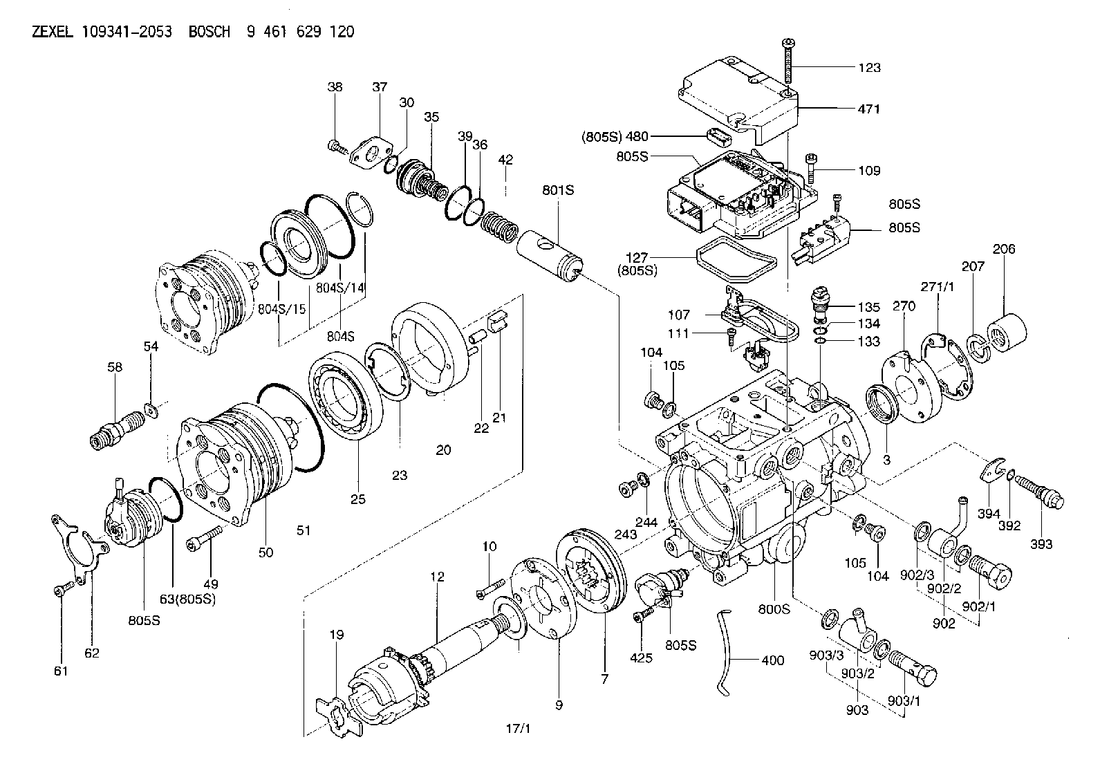
| 3. | [1] | 149351-0100 | PACKING RING |
| 3B. | [1] | 149351-0201 | PACKING RING |
| 7. | [1] | 149050-0220 | SUPPLY PUMP |
| 9. | [1] | 149055-0000 | SUPPORT RING |
| 10. | [4] | 149330-2000 | TORX SCREW |
| 12. | [1] | 149100-0520 | DRIVE SHAFT |
| 17/1. | [1] | 149110-0000 | SHIM D42.5627.1T2.2 |
| 17/1B. | [1] | 149110-0100 | SHIM D42.5&27.1T2.3 |
| 17/1C. | [1] | 149110-0200 | SHIM D42.5&27.1T2.4 |
| 17/1D. | [1] | 149110-0300 | SHIM D42.5&27.1T2.5 |
| 17/1E. | [1] | 149110-0400 | SHIM D42.5&27.1T2.6 |
| 17/1F. | [1] | 149110-0500 | SHIM D42.5&27.1T2.7 |
| 17/1G. | [1] | 149110-0600 | SHIM D42.5&27.1T2.8 |
| 17/1H. | [1] | 149110-0700 | SHIM D42.5&27.1T2.9 |
| 17/1I. | [1] | 149110-0800 | SHIM D42.5&27.1T3.0 |
| 17/1J. | [1] | 149110-0900 | SHIM D42.5&27.1T3.1 |
| 17/1K. | [1] | 149110-1000 | SHIM D42.5&27.1T3.2 |
| 17B/1. | [1] | 149110-1200 | SHIM D42.5&27.1T2.2 |
| 17B/1B. | [1] | 149110-1300 | SHIM D42.5&27.1T2.3 |
| 17B/1C. | [1] | 149110-1400 | SHIM D42.5&27.1T2.4 |
| 17B/1D. | [1] | 149110-1500 | SHIM D42.5&27.1T2.5 |
| 17B/1E. | [1] | 149110-1600 | SHIM D42.5&27.1T2.6 |
| 17B/1F. | [1] | 149110-1700 | SHIM D42.5&27.1T2.7 |
| 17B/1G. | [1] | 149110-1800 | SHIM D42.5&27.1T2.8 |
| 17B/1H. | [1] | 149110-1900 | SHIM D42.5&27.1T2.9 |
| 17B/1I. | [1] | 149110-2000 | SHIM D42.5&27.1T3.0 |
| 17B/1J. | [1] | 149110-2100 | SHIM D42.5&27.1T3.1 |
| 17B/1K. | [1] | 149110-2200 | SHIM D42.5&27.1T3.2 |
| 19. | [1] | 149111-0000 | DRIVER DISC |
| 20. | [1] | 149120-1120 | CAM RING |
| 21. | [2] | 149112-0200 | ROLLER SHOE |
| 22. | [2] | 149113-0200 | ROLLER |
| 22B. | [2] | 149113-0300 | ROLLER |
| 23. | [1] | 149111-0100 | PLATE |
| 25. | [1] | 149114-0000 | BEARING PLATE |
| 30. | [1] | 149350-3300 | O-RING |
| 35. | [1] | 149170-0022 | HYDRAULIC STOPPER |
| 36. | [1] | 149350-3400 | O-RING |
| 37. | [1] | 149180-0101 | CLOSING COVER |
| 38. | [2] | 149330-1800 | TORX BOLT |
| 39. | [1] | 149350-1700 | SEAL RING |
| 42. | [1] | 149164-0000 | COILED SPRING |
| 49. | [4] | 149330-1900 | TORX BOLT |
| 50. | [1] | 149200-1021 | HYDRAULIC HEAD |
| 51. | [3] | 149350-2000 | O-RING |
| 54. | [4] | 149313-2700 | GASKET |
| 58. | [4] | 149300-0023 | PRESSURE-CONTROL VALVE |
| 61. | [3] | 149330-2300 | TORX BOLT |
| 62. | [1] | 149436-0000 | PLATE |
| 63. | [1] | 149350-1900 | O-RING |
| 104. | [2] | 149330-2400 | HEX-SOCKET-HEAD CAP SCREW |
| 104. | [2] | 149330-2400 | HEX-SOCKET-HEAD CAP SCREW |
| 105. | [2] | 149443-0200 | GASKET |
| 105. | [2] | 149443-0200 | GASKET |
| 107. | [1] | 149403-0320 | SENSOR |
| 109. | [3] | 149330-1600 | TORX BOLT |
| 111. | [2] | 149330-0501 | TORX SCREW |
| 123. | [5] | 149330-1700 | TORX BOLT |
| 127. | [1] | 149350-2800 | SEAL RING |
| 133. | [1] | 149350-3500 | O-RING |
| 134. | [1] | 149350-3600 | O-RING |
| 135. | [1] | 149060-0020 | CONTROL VALVE |
| 206. | [1] | 149413-0001 | UNION NUT |
| 207. | [1] | 149412-0000 | PLAIN WASHER |
| 243. | [1] | 149330-2400 | HEX-SOCKET-HEAD CAP SCREW |
| 244. | [1] | 149443-0200 | GASKET |
| 270. | [1] | 149411-2500 | COUPLING PLATE |
| 271/1. | [1] | 149411-0200 | SHIM T0.5 |
| 271/1B. | [1] | 149411-0300 | SHIM T0.6 |
| 271/1C. | [1] | 149411-0400 | SHIM T0.7 |
| 271/1D. | [1] | 149411-0500 | SHIM T0.8 |
| 271/1E. | [1] | 149411-0600 | SHIM T0.9 |
| 271/1F. | [1] | 149411-0700 | SHIM T1.0 |
| 271/1G. | [1] | 149411-0800 | SHIM T1.1 |
| 271/1H. | [1] | 149411-0900 | SHIM T1.2 |
| 271/1I. | [1] | 149411-1000 | SHIM T1.3 |
| 271/1J. | [1] | 149411-1100 | SHIM T1.4 |
| 271/1K. | [1] | 149411-1200 | SHIM T1.5 |
| 271B/1. | [1] | 149411-2800 | SHIM T0.5 |
| 271B/1B. | [1] | 149411-2900 | SHIM T0.6 |
| 271B/1C. | [1] | 149411-3000 | SHIM T0.7 |
| 271B/1D. | [1] | 149411-3100 | SHIM T0.8 |
| 271B/1E. | [1] | 149411-3200 | SHIM T0.9 |
| 271B/1F. | [1] | 149411-3300 | SHIM T1.0 |
| 271B/1G. | [1] | 149411-3400 | SHIM T1.1 |
| 271B/1H. | [1] | 149411-3500 | SHIM T1.2 |
| 271B/1I. | [1] | 149411-3600 | SHIM T1.3 |
| 271B/1J. | [1] | 149411-3700 | SHIM T1.4 |
| 271B/1K. | [1] | 149411-3800 | SHIM T1.5 |
| 392. | [1] | 149350-3700 | O-RING |
| 393. | [1] | 149419-0100 | BLEEDER SCREW |
| 394. | [1] | 149420-0000 | INTERMEDIATE PLATE |
| 394B. | [1] | 149420-0100 | INTERMEDIATE PLATE |
| 400. | [1] | 149460-1300 | CABLE CRAMP |
| 425. | [2] | 149330-2200 | TORX BOLT |
| 471. | [1] | 149410-0000 | COVER |
| 480. | [1] | 149350-3800 | SEAL RING |
| 800S. | [1] | 149480-0620 | SERVICE PARTS GROUP |
| 801S. | [1] | 149481-0320 | PARTS SET |
| 804S. | [1] | 149483-0020 | PARTS SET |
| 804S/14. | [1] | 149350-1800 | O-RING |
| 804S/15. | [1] | 149350-1900 | O-RING |
| 805S. | [1] | 149482-0020 | PARTS SET |
| 805S. | [1] | 149482-0020 | PARTS SET |
| 805S. | [1] | 149482-0020 | PARTS SET |
| 805S. | [1] | 149482-0020 | PARTS SET |
| 805S. | [1] | 149482-0020 | PARTS SET |
| 805S. | [1] | 149482-0020 | PARTS SET |
| 805S. | [1] | 149482-0020 | PARTS SET |
| 805S. | [1] | 149482-0020 | PARTS SET |
| 902. | [1] | 149433-0220 | OUTLET PIPE ASSY |
| 902/1. | [1] | 149070-0120 | OVER FLOW VALVE |
| 902/2. | [1] | 146669-4420 | INLET UNION |
| 902/3. | [2] | 149350-2700 | FLAT SEAL RING |
| 903. | [1] | 149428-0220 | INLET PIPE |
| 903/1. | [1] | 149330-0000 | EYE BOLT |
| 903/2. | [1] | 146669-4320 | INLET UNION |
| 903/3. | [2] | 149350-2600 | FLAT SEAL RING |
Include in #2:
109341-2053
as INJECTION-PUMP ASSEMBLY
Cross reference number
Zexel num
Bosch num
Firm num
Name
9 461 629 120
A67005M321 NISSAN
INJECTION-PUMP ASSEMBLY
K 13CJ INJECTION PUMP ASSY VP44 VP44
K 13CJ INJECTION PUMP ASSY VP44 VP44
9 461 629 120
167005M321 NISSAN
INJECTION-PUMP ASSEMBLY
A K 13CJ INJECTION PUMP ASSY VP44 VP44
A K 13CJ INJECTION PUMP ASSY VP44 VP44
9 461 629 120
167005M321 NISSAN-DIESEL
INJECTION-PUMP ASSEMBLY
K 13CJ INJECTION PUMP ASSY VP44 VP44
K 13CJ INJECTION PUMP ASSY VP44 VP44
Information:
Delco-Remy Alternator; Pulley Nut Tightening
Tighten nut holding the pulley to a torque of 75 5 lb. ft. (100 7 N m) with the tools shown.
ALTERNATOR PULLEY INSTALLATION
1. 8S1588 Adapter (1/2" female to 3/8" male). 2. 8S1590 Socket (5/16" with 3/8" drive). 3. 1P2977 Tool Group. 8H8555 Socket (15/16" with 1/2" drive) not shown.Alternator Regulator Adjustment (Delco-Remy)
Set Screw Type
When an alternator is charging the battery too much or not enough, an adjustment can be made to the charging rate of the alternator. Remove the hollow head screw (1) from the alternator and use a screwdriver to turn the adjustment screw. Turn the adjustment screw one or two notches to increase or decrease the charging rate of the alternator.
LOCATION OF ADJUSTMENT SCREW FOR THE ALTERNATOR REGULATOR
1. Hollow head screw. 2. Connector.Cap Type
ALTERNATOR REGULATOR ADJUSTMENT
1. Voltage adjustment cap.When the alternator is either charging the battery too much or not enough, an adjustment can be made to the alternator charging rate. To make an adjustment to the voltage output, remove the voltage adjustment cap (1) from the alternator, turn the cap 90°, and install it again into the alternator. The voltage adjustment cap has four positions: HI, LO, and two positions between the high and the low setting.Alternator Regulator (Prestolite)
ALTERNATOR REGULATOR
1. Adjustment screw with washer. 2. High output position. 3. Green wire to field terminal of the alternator (F). 4. Orange wire to battery. 5. Black wire to ground.The regulator components are sealed in an insulation of epoxy. The regulator is an electronic component with no moving parts (solid state) and has an adjustment screw (1) on the back. This voltage adjustment screw is used to meet different operating needs at different times of the year. An increase or decrease by .5 volts from the normal (N) setting is made by removing the regulator and changing the position of the adjustment screw and washer. An increase to the voltage will be made by moving the screw and washer to the "H" position (2).Starting System
5P300 Electrical Tester. Make reference to Special Instruction Form No. SEHS7006 and to the instructions inside of the cover of the tester, when testing with the 5P300 Electrical Tester.Use a D.C. Voltmeter to find starting system components which do not function.Move the starting control switch to activate the starter solenoid. Starter solenoid operation can be heard as the pinion of the starter motor is engaged with the ring gear on the engine flywheel. The solenoid operation also closes the electric circuit to the motor. Connect one wire of the voltmeter to the solenoid connection (terminal) that is fastened to the motor. Connect the other wire to a good ground. Activate the starter solenoid and look at the voltmeter. A reading of battery voltage shows the problem is in the motor. The motor must be removed for more testing. No reading on the voltmeter shows that the solenoid contacts do not close. This is an indication of the need for repair to the solenoid or of an adjustment