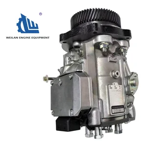
Information injection-pump assembly
BOSCH
0 470 504 037
0470504037
ZEXEL
109341-1024
1093411024
ISUZU
8973267393
8973267393

Rating:
Compare Prices: .
As an associate, we earn commssions on qualifying purchases through the links below

Fuel Injector Pump 8973267393 for Isuzu Engine 4JH1 3.0 D Truck D-MAX FVR
FGNTWP Part Number:8973267390, 8973267391, 8973267392, 8973267393, 8973267394, 8973267395, 8-97326739-0, 8973267391, 8-97326739-2, 8-97326739-3, 8-97326739-4, 8-97326739-5, 0 470 504 037, 0470504037, 109341-1020, 1093411020, 109341-1021, 1093411021 , 109341-1022, 1093411022 , 109341-1023, 1093411023, 109341-1024, 1093411024, 109341-1025, 1093411025 || Application:for Isuzu Engine 4JH1 3.0 D Truck D-MAX FVR
FGNTWP Part Number:8973267390, 8973267391, 8973267392, 8973267393, 8973267394, 8973267395, 8-97326739-0, 8973267391, 8-97326739-2, 8-97326739-3, 8-97326739-4, 8-97326739-5, 0 470 504 037, 0470504037, 109341-1020, 1093411020, 109341-1021, 1093411021 , 109341-1022, 1093411022 , 109341-1023, 1093411023, 109341-1024, 1093411024, 109341-1025, 1093411025 || Application:for Isuzu Engine 4JH1 3.0 D Truck D-MAX FVR

Compatible with Isuzu 4JH1 D-Max 3.0 DiTD 120 Kw Engine VP44 Fuel Injection Pump 0470504037 8973267393 109341-1024 Fits
EWAIDI Part Number:0470504037 8973267393 109341-1024 || Application:Fits for Isuzu 4JH1 D-Max 3.0 DiTD 120 Kw Engine || The VP44 Fuel Injection Pump is a vital component in diesel engine fuel delivery, ensuring precise fuel delivery for efficient combustion. Its rotary design generates high-pressure fuel pulses for injector distribution, known for reliability. Regular maintenance is essential for optimal performance. || Note that the application information presented serves as a guide. It is advised to verify the part number and conduct a comparison with the existing parts prior to making a purchase. Should you have any inquiries, do not hesitate to reach out to us. || Great Value- This item offers consistent performance, excellent reliability, simple installation, and quick response time.
EWAIDI Part Number:0470504037 8973267393 109341-1024 || Application:Fits for Isuzu 4JH1 D-Max 3.0 DiTD 120 Kw Engine || The VP44 Fuel Injection Pump is a vital component in diesel engine fuel delivery, ensuring precise fuel delivery for efficient combustion. Its rotary design generates high-pressure fuel pulses for injector distribution, known for reliability. Regular maintenance is essential for optimal performance. || Note that the application information presented serves as a guide. It is advised to verify the part number and conduct a comparison with the existing parts prior to making a purchase. Should you have any inquiries, do not hesitate to reach out to us. || Great Value- This item offers consistent performance, excellent reliability, simple installation, and quick response time.

VP44 Fuel Injection Pump Compatible with Isuzu D-Max 4JH1 3.0L Engine 109341-1024 0470504048 8973267390 8-97326-739-0
EWAIDI Part Number: 0470504048 109341-1024 8973267390 8-97326-739-0 || Engine Model: for Isuzu D-Max 4JH1 3.0L Engine || The VP44 Diesel Fuel Distributor Injection Pump is a vital component in diesel vehicles, delivering fuel to injectors for optimal engine performance. Known for reliability and durability, regular maintenance is essential to prevent issues. This high-pressure pump plays a key role in combustion, ensuring fuel efficiency and smooth engine operation. || for verification. It is important to ensure compatibility and avoid any potential issues with your purchase. Thank you for your attention to detail and cooperation. || Service: We offer a generous 5-month warranty on all our products, along with round-the-clock customer support. If you have any questions or concerns, please don't hesitate to reach out to us via email.
EWAIDI Part Number: 0470504048 109341-1024 8973267390 8-97326-739-0 || Engine Model: for Isuzu D-Max 4JH1 3.0L Engine || The VP44 Diesel Fuel Distributor Injection Pump is a vital component in diesel vehicles, delivering fuel to injectors for optimal engine performance. Known for reliability and durability, regular maintenance is essential to prevent issues. This high-pressure pump plays a key role in combustion, ensuring fuel efficiency and smooth engine operation. || for verification. It is important to ensure compatibility and avoid any potential issues with your purchase. Thank you for your attention to detail and cooperation. || Service: We offer a generous 5-month warranty on all our products, along with round-the-clock customer support. If you have any questions or concerns, please don't hesitate to reach out to us via email.
You can express buy:
USD 2414.78
27-06-2025
27-06-2025
Original VP44 Fuel Pump 0470504037 0 470 504 037 for ISUZU D-Max 8973267393 8-97326739-3 ZEXEL 109341-1024
Images:
USD 809.5

[14-Jun-2025]
USD 1159.89

[14-Jun-2025]
USD 596.32

[14-Jun-2025]
Components :
| 0. | INJECTION-PUMP ASSEMBLY | 109341-1024 |
| 1. | _ | |
| 2. | FUEL INJECTION PUMP | 109241-1006 |
| 3. | NUMBER PLATE | |
| 4. | _ | |
| 5. | CAPSULE | |
| 6. | ADJUSTING DEVICE | |
| 7. | NOZZLE AND HOLDER ASSY | 105118-8212 |
| 8. | Nozzle and Holder | |
| 9. | Open Pre:MPa(Kqf/cm2) | 19.5{199}/33.8{345} |
| 10. | NOZZLE-HOLDER | 105048-2270 |
| 11. | NOZZLE | 105017-3090 |
Scheme ###:
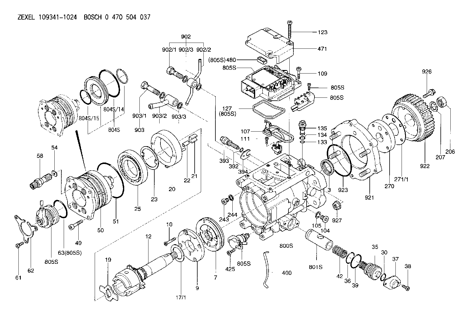
| 3. | [1] | 149351-0201 | PACKING RING |
| 7. | [1] | 149050-0220 | SUPPLY PUMP |
| 9. | [1] | 149055-0000 | SUPPORT RING |
| 10. | [4] | 149330-2000 | TORX SCREW |
| 12. | [1] | 149100-1120 | DRIVE SHAFT |
| 17/1. | [1] | 149110-0000 | SHIM D42.5627.1T2.2 |
| 17/1B. | [1] | 149110-0100 | SHIM D42.5&27.1T2.3 |
| 17/1C. | [1] | 149110-0200 | SHIM D42.5&27.1T2.4 |
| 17/1D. | [1] | 149110-0300 | SHIM D42.5&27.1T2.5 |
| 17/1E. | [1] | 149110-0400 | SHIM D42.5&27.1T2.6 |
| 17/1F. | [1] | 149110-0500 | SHIM D42.5&27.1T2.7 |
| 17/1G. | [1] | 149110-0600 | SHIM D42.5&27.1T2.8 |
| 17/1H. | [1] | 149110-0700 | SHIM D42.5&27.1T2.9 |
| 17/1I. | [1] | 149110-0800 | SHIM D42.5&27.1T3.0 |
| 17/1J. | [1] | 149110-0900 | SHIM D42.5&27.1T3.1 |
| 17/1K. | [1] | 149110-1000 | SHIM D42.5&27.1T3.2 |
| 17B/1. | [1] | 149110-1200 | SHIM D42.5&27.1T2.2 |
| 17B/1B. | [1] | 149110-1300 | SHIM D42.5&27.1T2.3 |
| 17B/1C. | [1] | 149110-1400 | SHIM D42.5&27.1T2.4 |
| 17B/1D. | [1] | 149110-1500 | SHIM D42.5&27.1T2.5 |
| 17B/1E. | [1] | 149110-1600 | SHIM D42.5&27.1T2.6 |
| 17B/1F. | [1] | 149110-1700 | SHIM D42.5&27.1T2.7 |
| 17B/1G. | [1] | 149110-1800 | SHIM D42.5&27.1T2.8 |
| 17B/1H. | [1] | 149110-1900 | SHIM D42.5&27.1T2.9 |
| 17B/1I. | [1] | 149110-2000 | SHIM D42.5&27.1T3.0 |
| 17B/1J. | [1] | 149110-2100 | SHIM D42.5&27.1T3.1 |
| 17B/1K. | [1] | 149110-2200 | SHIM D42.5&27.1T3.2 |
| 19. | [1] | 149111-0000 | DRIVER DISC |
| 20. | [1] | 149120-0820 | CAM RING |
| 21. | [2] | 149112-0200 | ROLLER SHOE |
| 22. | [2] | 149113-0300 | ROLLER |
| 23. | [1] | 149111-0100 | PLATE |
| 25. | [1] | 149114-0000 | BEARING PLATE |
| 30. | [1] | 149350-3300 | O-RING |
| 35. | [1] | 149170-0022 | HYDRAULIC STOPPER |
| 36. | [1] | 149350-3400 | O-RING |
| 37. | [1] | 149180-0300 | CLOSING COVER |
| 38. | [2] | 149330-2900 | TORX BOLT |
| 39. | [1] | 149350-1700 | SEAL RING |
| 42. | [1] | 149164-0000 | COILED SPRING |
| 49. | [4] | 149330-3900 | TORX BOLT |
| 50. | [1] | 149201-0522 | HYDRAULIC HEAD |
| 51. | [3] | 149350-2000 | O-RING |
| 54. | [4] | 149313-2700 | GASKET |
| 58. | [4] | 149300-1120 | PRESSURE-CONTROL VALVE |
| 61. | [3] | 149330-3400 | TORX BOLT |
| 62. | [1] | 149436-0100 | PLATE |
| 63. | [1] | 149350-1900 | O-RING |
| 104. | [2] | 149330-3500 | HEX-SOCKET-HEAD CAP SCREW |
| 105. | [2] | 149443-0200 | GASKET |
| 107. | [1] | 149403-0420 | SENSOR |
| 109. | [3] | 149330-1600 | TORX BOLT |
| 111. | [2] | 149330-0501 | TORX SCREW |
| 123. | [5] | 149330-3900 | TORX BOLT |
| 127. | [1] | 149350-2800 | SEAL RING |
| 133. | [1] | 149350-3500 | O-RING |
| 134. | [1] | 149350-3600 | O-RING |
| 135. | [1] | 149060-0520 | CONTROL VALVE |
| 206. | [1] | 149330-2500 | UNION NUT |
| 207. | [1] | 149412-0100 | PLAIN WASHER |
| 243. | [1] | 149330-3500 | HEX-SOCKET-HEAD CAP SCREW |
| 244. | [1] | 149443-0200 | GASKET |
| 270. | [1] | 149411-2500 | COUPLING PLATE |
| 271/1. | [1] | 149411-0200 | SHIM T0.5 |
| 271/1B. | [1] | 149411-0300 | SHIM T0.6 |
| 271/1C. | [1] | 149411-0400 | SHIM T0.7 |
| 271/1D. | [1] | 149411-0500 | SHIM T0.8 |
| 271/1E. | [1] | 149411-0600 | SHIM T0.9 |
| 271/1F. | [1] | 149411-0700 | SHIM T1.0 |
| 271/1G. | [1] | 149411-0800 | SHIM T1.1 |
| 271/1H. | [1] | 149411-0900 | SHIM T1.2 |
| 271/1I. | [1] | 149411-1000 | SHIM T1.3 |
| 271/1J. | [1] | 149411-1100 | SHIM T1.4 |
| 271/1K. | [1] | 149411-1200 | SHIM T1.5 |
| 271B/1. | [1] | 149411-2800 | SHIM T0.5 |
| 271B/1B. | [1] | 149411-2900 | SHIM T0.6 |
| 271B/1C. | [1] | 149411-3000 | SHIM T0.7 |
| 271B/1D. | [1] | 149411-3100 | SHIM T0.8 |
| 271B/1E. | [1] | 149411-3200 | SHIM T0.9 |
| 271B/1F. | [1] | 149411-3300 | SHIM T1.0 |
| 271B/1G. | [1] | 149411-3400 | SHIM T1.1 |
| 271B/1H. | [1] | 149411-3500 | SHIM T1.2 |
| 271B/1I. | [1] | 149411-3600 | SHIM T1.3 |
| 271B/1J. | [1] | 149411-3700 | SHIM T1.4 |
| 271B/1K. | [1] | 149411-3800 | SHIM T1.5 |
| 392. | [1] | 149350-3700 | O-RING |
| 393. | [1] | 149419-0600 | BLEEDER SCREW |
| 394. | [1] | 149420-0001 | INTERMEDIATE PLATE |
| 400. | [1] | 149460-1300 | CABLE CRAMP |
| 425. | [2] | 149330-3300 | TORX BOLT |
| 471. | [1] | 149410-0000 | COVER |
| 480. | [1] | 149350-3800 | SEAL RING |
| 800S. | [1] | 149480-0020 | SERVICE PARTS GROUP |
| 801S. | [1] | 149481-0220 | PARTS SET |
| 804S. | [1] | 149483-0020 | PARTS SET |
| 804S/14. | [1] | 149350-1800 | O-RING |
| 804S/15. | [1] | 149350-1900 | O-RING |
| 805S. | [1] | 149482-0220 | PARTS SET |
| 805S. | [1] | 149482-0220 | PARTS SET |
| 805S. | [1] | 149482-0220 | PARTS SET |
| 805S. | [1] | 149482-0220 | PARTS SET |
| 805S. | [1] | 149482-0220 | PARTS SET |
| 805S. | [1] | 149482-0220 | PARTS SET |
| 805S. | [1] | 149482-0220 | PARTS SET |
| 805S. | [1] | 149482-0220 | PARTS SET |
| 902. | [1] | 149433-0021 | OUTLET PIPE ASSY |
| 902/1. | [1] | 149070-0120 | OVER FLOW VALVE |
| 902/2. | [1] | 149430-0120 | INLET UNION |
| 902/3. | [2] | 149350-2700 | FLAT SEAL RING |
| 903. | [1] | 149428-0021 | INLET PIPE |
| 903/1. | [1] | 149071-0120 | EYE BOLT |
| 903/2. | [1] | 149425-0920 | INLET UNION |
| 903/3. | [2] | 149350-2600 | FLAT SEAL RING |
| 921. | [1] | 149465-0222 | BRACKET |
| 922. | [1] | 149470-0200 | TOOTHED GEAR |
| 923. | [1] | 149350-1400 | O-RING |
| 926. | [4] | 149442-0101 | BLEEDER SCREW |
| 927. | [4] | 149413-0101 | UNION NUT |
Include in #2:
109341-1024
as INJECTION-PUMP ASSEMBLY
Cross reference number
Zexel num
Bosch num
Firm num
Name
109341-1024
0 470 504 037
8973267393 ISUZU
INJECTION-PUMP ASSEMBLY
4JH1TC K 13CJ VP44 VP44
4JH1TC K 13CJ VP44 VP44
Information:
start by:a) remove timing gear cover1. Remove the turbocharger return tube from the flywheel housing. 2. Remove two studs (1).3. Turn the engine with tool (A) to remove four bolts (2) from the rear balance weight gear.4. Turn the engine again with tool (A) until the "V" marks on all the timing gears are in alignment with each other.5. With the timing marks in alignment, install tooling (B) in the location of rear studs (1). Make sure the bolts [tooling (B)] are in the rear balance weight gear. Tighten the bolts [tooling (B)] evenly until the rear balance weight gear is free of the camshaft. 6. Remove bolts (3) and thrust plate (4). Pull the camshaft forward as far as possible [approximately 1/4 in. (6.4 mm)]. 7. Remove four bolts (6) and plate (7).8. Remove bolts (5) and the thrust plates that hold balance gear (8) in position. The gear must be pulled forward as bolts (5) are removed.9. After bolts (5) are all removed, remove balance gear (8). If balance gear (8) can not be removed turn the engine a small amount with tool (A) until the gear is free.10. Remove the bearing from balance gear (8) with tooling (D) and an arbor press. 11. Remove crankshaft gear (9) with tool (C).Install Timing Gears
1. Install the bearing in the front balance gear with tooling (A) and an arbor press. The bearing joint must be on a center line of the balance gear with in 20°.2. Heat crankshaft gear (3) to a maximum temperature of 400°F (204°C). Install the gear with the notch in the gear in alignment with the pin in the crankshaft. 3. Install shaft (1) in balance gear (2). Install the bolts in the shaft. Put the complete unit in position behind the camshaft gear as shown. Make sure the "V" mark on the two gears are in alignment with each other. Tighten the bolts that hold the balance gear in position. 4. Install plate (5) and the four bolts that hold the balance gear to the shaft. Make sure the groove in the plate is toward the gear.5. Push the camshaft toward the rear of the engine. Install thrust plate (4) and the bolts that hold the camshaft in position. Make sure the "V" mark on the camshaft gear is in alignment with the "V" mark on the balance gear.6. Remove tooling (C) (the two bolts) from the rear balance weight gear. Turn the engine with tool (B) to install the four bolts that hold the rear balance weight gear to the camshaft.7. Install the two studs in the flywheel housing.8. Install the turbocharger return tube assembly.end by:a) install timing gear cover
1. Install the bearing in the front balance gear with tooling (A) and an arbor press. The bearing joint must be on a center line of the balance gear with in 20°.2. Heat crankshaft gear (3) to a maximum temperature of 400°F (204°C). Install the gear with the notch in the gear in alignment with the pin in the crankshaft. 3. Install shaft (1) in balance gear (2). Install the bolts in the shaft. Put the complete unit in position behind the camshaft gear as shown. Make sure the "V" mark on the two gears are in alignment with each other. Tighten the bolts that hold the balance gear in position. 4. Install plate (5) and the four bolts that hold the balance gear to the shaft. Make sure the groove in the plate is toward the gear.5. Push the camshaft toward the rear of the engine. Install thrust plate (4) and the bolts that hold the camshaft in position. Make sure the "V" mark on the camshaft gear is in alignment with the "V" mark on the balance gear.6. Remove tooling (C) (the two bolts) from the rear balance weight gear. Turn the engine with tool (B) to install the four bolts that hold the rear balance weight gear to the camshaft.7. Install the two studs in the flywheel housing.8. Install the turbocharger return tube assembly.end by:a) install timing gear cover
Have questions with 109341-1024?
Group cross 109341-1024 ZEXEL
Isuzu
109341-1024
0 470 504 037
8973267393
INJECTION-PUMP ASSEMBLY
4JH1TC
4JH1TC