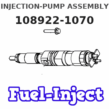
Information injection-pump assembly
ZEXEL
108922-1070
1089221070
Rating:
Cross reference number
ZEXEL
108922-1070
1089221070
Zexel num
Bosch num
Firm num
Name
Calibration Data:
Adjustment conditions
Test oil
1404 Test oil ISO4113 or {SAEJ967d}
1404 Test oil ISO4113 or {SAEJ967d}
Test oil temperature
degC
40
40
45
Nozzle and nozzle holder
105780-8250
Bosch type code
1 688 901 101
Nozzle
105780-0120
Bosch type code
1 688 901 990
Nozzle holder
105780-2190
Opening pressure
MPa
20.7
Opening pressure
kgf/cm2
211
Injection pipe
Outer diameter - inner diameter - length (mm) mm 8-3-600
Outer diameter - inner diameter - length (mm) mm 8-3-600
Overflow valve
134424-4320
Overflow valve opening pressure
kPa
255
221
289
Overflow valve opening pressure
kgf/cm2
2.6
2.25
2.95
Tester oil delivery pressure
kPa
255
255
255
Tester oil delivery pressure
kgf/cm2
2.6
2.6
2.6
RED4 control unit part number
407915-0
590
RED4 rack sensor specifications
mm
19
PS/ACT control unit part no.
407980-2
24*
Digi switch no.
52
Direction of rotation (viewed from drive side)
Right R
Right R
Injection timing adjustment
Direction of rotation (viewed from drive side)
Right R
Right R
Injection order
1-8-7-6-
5-4-3-10
-9-2
Pre-stroke
mm
8
7.97
8.03
Beginning of injection position
Governor side NO.1
Governor side NO.1
Difference between angles 1
Cal 1-8 deg. 27 26.75 27.25
Cal 1-8 deg. 27 26.75 27.25
Difference between angles 2
Cal 1-7 deg. 72 71.75 72.25
Cal 1-7 deg. 72 71.75 72.25
Difference between angles 3
Cal 1-6 deg. 99 98.75 99.25
Cal 1-6 deg. 99 98.75 99.25
Difference between angles 4
Cal 1-5 deg. 144 143.75 144.25
Cal 1-5 deg. 144 143.75 144.25
Difference between angles 5
Cal 1-4 deg. 171 170.75 171.25
Cal 1-4 deg. 171 170.75 171.25
Difference between angles 6
Cal 1-3 deg. 216 215.75 216.25
Cal 1-3 deg. 216 215.75 216.25
Difference between angles 7
Cal 1-10 deg. 243 242.75 243.25
Cal 1-10 deg. 243 242.75 243.25
Difference between angles 8
Cal 1-9 deg. 288 287.75 288.25
Cal 1-9 deg. 288 287.75 288.25
Difference between angles 9
Cyl.1-2 deg. 315 314.75 315.25
Cyl.1-2 deg. 315 314.75 315.25
Injection quantity adjustment
Rack position
(12.1)
PWM
%
56.1
Pump speed
r/min
700
700
700
Average injection quantity
mm3/st.
138
137
139
Max. variation between cylinders
%
0
-3
3
Basic
*
PS407980-224*
V
2.2+-0.0
1
PS407980-224*
mm
5.6+-0.0
5
Injection quantity adjustment_02
Rack position
(6.7)
PWM
%
26+-2.8
Pump speed
r/min
400
400
400
Average injection quantity
mm3/st.
11
9
13
Max. variation between cylinders
%
0
-13
13
PS407980-224*
V
V1+0.05+
-0.01
PS407980-224*
mm
7.9+-0.0
3
Remarks
Refer to items regarding the pre-stroke actuator
Refer to items regarding the pre-stroke actuator
0000001201
Pre-stroke
mm
8
7.97
8.03
Remarks
When the timing sleeve is pushed up
When the timing sleeve is pushed up
_02
Connector angle
deg.
11.5
11
12
Remarks
When the eccentric pin is tightened
When the eccentric pin is tightened
_03
Supply voltage
V
24
23.5
24.5
Ambient temperature
degC
23
18
28
Pre-stroke
mm
4
3.95
4.05
Output voltage
V
2.95
2.94
2.96
Adjustment
*
_04
Supply voltage
V
24
23.5
24.5
Ambient temperature
degC
23
18
28
Pre-stroke
mm
8
7.97
8.03
Output voltage
V
1.2
1
1.4
Confirmation
*
Remarks
Output voltage V1
Output voltage V1
_05
Supply voltage
V
24
23.5
24.5
Ambient temperature
degC
23
18
28
Output voltage
V
3.05
3.05
Confirmation of operating range
*
Test data Ex:
Speed control lever angle

N:Pump normal
S:Stop the pump.
(1)Rack position = aa
(2)Rack position bb
----------
aa=20mm bb=1mm
----------
a=37deg+-5deg b=37deg+-5deg
----------
aa=20mm bb=1mm
----------
a=37deg+-5deg b=37deg+-5deg
0000000901

(1)Pump vertical direction
(2)Position of gear mark 'Z' at No 1 cylinder's beginning of injection
(3)B.T.D.C.: aa
(4)Pre-stroke: bb
----------
aa=4deg bb=8+-0.03mm
----------
a=(170deg)
----------
aa=4deg bb=8+-0.03mm
----------
a=(170deg)
0000001501

A:Sealing position
B:Pre-stroke actuator
1. When installing the pre-stroke actuator on the pump, first tighten the installation bolts loosely, then move the actuator fully counterclockwise (viewed from the drive side).
Temporary tightening torque: 1 - 1.5 N.m (0.1 - 0.15 kgf.m)
2. Move the actuator in the clockwise direction when viewed from the drive side, and adjust so that it becomes the adjustment point of the adjustment value. Then tighten it.
Tightening torque: 7^9 N.m (0.7^0.9 kgf.m)
3. After prestroke actuator installation adjustment, simultaneously stamp both the actuator side and housing side.
----------
----------
----------
----------
0000001701

(PWM) Pulse width modulation (%)
(R) Rack position (mm)
Rack sensor output characteristics
1. Rack limit adjustment
(1)Measure the rack position R2 for PWM a2%.
(2)Confirm that it is within the range R2 = 15+-1 mm.
(3)Measure the rack position R1 at PWM a %.
(4)Confirm that it is within the range R2 - R1 = 10+-0.1 mm.
2. Check the limp home operation.
(1)Move the switch box's limp home switch to the limp home side.
(2)Confirm rack position L1 (mm ) and L2 (mm) for PWM in the above table.
3. Check the pull down operation.
(1)Confirm that the rack position is 19 mm at PWM B%.
(2)In the conditions described in the above table, move the switch box's pull down switch to the pull down side and confirm that the rack position momentarily becomes 1 mm or less.
----------
a1=16.25 % a2=72.5 % L1=1-- mm L2=19++mm A=5 % B=95 %
----------
----------
a1=16.25 % a2=72.5 % L1=1-- mm L2=19++mm A=5 % B=95 %
----------
Information:
APRIL 2010
INFORMATION RELEASE MEMO
Reman
PELJ1163 ?2010 Caterpillar CAT REMAN ANNOUNCES AN APPEARANCE CHANGE TO MECHANICAL UNIT INJECTORS FOR 3600 ENGINES
Announcement
In the past, Reman 3600 mechanical unit injectors consistently had only one drill hole in the body. Effective immediately, dealers will now see some bodies with one drill hole and some bodies with two drill holes. Validation tests confirm the number of drill holes will not impact quality, reliability, durability, fit, or performance. Affected part numbers are listed in the table below.
* For serial number specific information please see SISWEB.
Effective immediately, Figure 1 and Figure 2 will both represent acceptable 3600 mechanical unit injector appearances.
Features and Benefits
Cat? Reman Fuel Injectors offer excellent value to customers. Customers who want fast repair turn-around, superior quality and reliability, and lower repair costs will benefit from the use of these remanufactured fuel transfer pumps. Cat Reman Fuel Injectors provide immediate, off-the-shelf availability at a fraction of the new price.
Features Benefits
All critical engineering changes and updates included Improved reliability and performance
Worldwide availability through Cat parts distribution system Customer access regardless of location
Backed by Caterpillar parts warranty Consistent support
Core Acceptance
Core Acceptance Criteria for Caterpillar Remanufactured Mechanical Unit Injectors is simple, visual, and requires no special tools. Consult the Unit Injectors ? Mechanical Core Acceptance Criteria SELD0030 for complete details.
Warranty
Please consult the appropriate Cat parts warranty statement for your area.
Core Management
Please refer to the Cat Core Management Information System (CMIS 2) Parts Information application describing all Cat Reman part/CAF and related information. Also refer to other CMIS 2 inquiry applications such as Customer Profiles, Inspection Reason Codes, Inspection Line Inquiry, Add Charge Information, Entitlement Activity, Entitlement Inquiry, CCR Inquiry, CCR Entry, Shipment Processing; Process Packaging Grief; and Reporting to properly manage core returns and monitor inspection performance. This information will be available to all dealers worldwide after your CMIS 2 conversion date. In the meantime, please continue to use the current CMIS Entitlement Parts Inquiry Screen describing the list of parts in a Core Acceptability Family (CAF) and related part number detail.
For the latest updates of Reman Policies and Core Management (SELD0122), Core Management Systems & Operations Procedures (SELD0040), and Shipping Instructions (SELD0039), go to the Reman Dealer website https://catreman.cat.com. If you have any questions regarding core return processing, feel free to call Corinth toll free at (800) 537-2928. Outside the US please refer to the Core section of the Reman website for appropriate contact information for your region.
For assistance with technical questions, call the Peoria Reman Technical Help Line also toll free at (888) 88-REMAN (outside the US call non-toll free +1-309-494-4342), or use our E-mail address--Reman_Help.