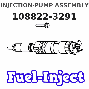
Information injection-pump assembly
ZEXEL
108822-3291
1088223291
HINO
220401751A
220401751a
Rating:
Cross reference number
ZEXEL
108822-3291
1088223291
HINO
220401751A
220401751a
Zexel num
Bosch num
Firm num
Name
Calibration Data:
Adjustment conditions
Test oil
1404 Test oil ISO4113 or {SAEJ967d}
1404 Test oil ISO4113 or {SAEJ967d}
Test oil temperature
degC
40
40
45
Nozzle and nozzle holder
105780-8250
Bosch type code
1 688 901 101
Nozzle
105780-0120
Bosch type code
1 688 901 990
Nozzle holder
105780-2190
Opening pressure
MPa
20.7
Opening pressure
kgf/cm2
211
Injection pipe
Outer diameter - inner diameter - length (mm) mm 8-3-600
Outer diameter - inner diameter - length (mm) mm 8-3-600
Overflow valve
134424-4120
Overflow valve opening pressure
kPa
255
221
289
Overflow valve opening pressure
kgf/cm2
2.6
2.25
2.95
Tester oil delivery pressure
kPa
255
255
255
Tester oil delivery pressure
kgf/cm2
2.6
2.6
2.6
RED4 control unit part number
407915-0
590
RED4 rack sensor specifications
mm
19
PS/ACT control unit part no.
407980-2
24*
Digi switch no.
41
Direction of rotation (viewed from drive side)
Right R
Right R
Injection timing adjustment
Direction of rotation (viewed from drive side)
Right R
Right R
Injection order
1-8-6-2-
7-5-4-3
Pre-stroke
mm
6.4
6.37
6.43
Beginning of injection position
Drive side NO.1
Drive side NO.1
Difference between angles 1
Cal 1-8 deg. 45 44.75 45.25
Cal 1-8 deg. 45 44.75 45.25
Difference between angles 2
Cal 1-6 deg. 90 89.75 90.25
Cal 1-6 deg. 90 89.75 90.25
Difference between angles 3
Cyl.1-2 deg. 135 134.75 135.25
Cyl.1-2 deg. 135 134.75 135.25
Difference between angles 4
Cal 1-7 deg. 180 179.75 180.25
Cal 1-7 deg. 180 179.75 180.25
Difference between angles 5
Cal 1-5 deg. 225 224.75 225.25
Cal 1-5 deg. 225 224.75 225.25
Difference between angles 6
Cal 1-4 deg. 270 269.75 270.25
Cal 1-4 deg. 270 269.75 270.25
Difference between angles 7
Cal 1-3 deg. 315 314.75 315.25
Cal 1-3 deg. 315 314.75 315.25
Injection quantity adjustment
Rack position
(12.9)
PWM
%
60.5
Pump speed
r/min
700
700
700
Average injection quantity
mm3/st.
150
148
152
Max. variation between cylinders
%
0
-3
3
Basic
*
PS407980-224*
V
2.2+-0.0
1
PS407980-224*
mm
4+-0.05
Injection quantity adjustment_02
Rack position
(6.9)
PWM
%
26.8+-2.
8
Pump speed
r/min
340
340
340
Average injection quantity
mm3/st.
20.5
19.5
21.5
Max. variation between cylinders
%
0
-10
10
PS407980-224*
V
V1+0.05+
-0.01
PS407980-224*
mm
6.3+-0.0
3
Remarks
Refer to items regarding the pre-stroke actuator
Refer to items regarding the pre-stroke actuator
0000001201
Pre-stroke
mm
6.4
6.37
6.43
Remarks
When the timing sleeve is pushed up
When the timing sleeve is pushed up
_02
Connector angle
deg.
8.5
8
9
Remarks
When the eccentric pin is tightened
When the eccentric pin is tightened
_03
Supply voltage
V
24
23.5
24.5
Ambient temperature
degC
23
18
28
Pre-stroke
mm
2.4
2.35
2.45
Output voltage
V
2.95
2.94
2.96
Adjustment
*
_04
Supply voltage
V
24
23.5
24.5
Ambient temperature
degC
23
18
28
Pre-stroke
mm
6.4
6.37
6.43
Output voltage
V
1.2
1
1.4
Confirmation
*
Remarks
Output voltage V1
Output voltage V1
_05
Supply voltage
V
24
23.5
24.5
Ambient temperature
degC
23
18
28
Output voltage
V
3.05
3.05
Confirmation of operating range
*
Test data Ex:
Speed control lever angle
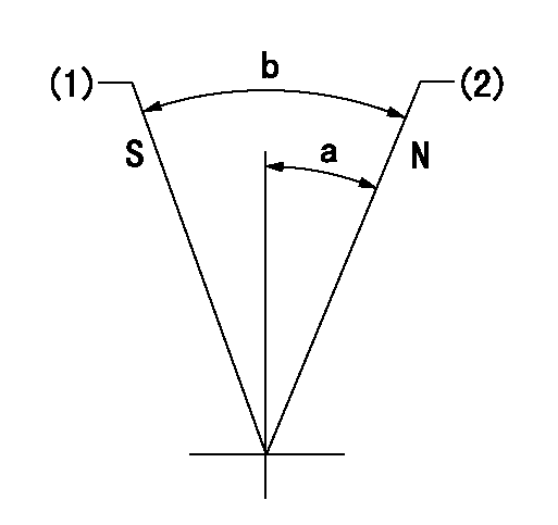
N:Pump normal
S:Stop the pump.
(1)Rack position = aa
(2)Rack position bb
----------
aa=1mm bb=20mm
----------
a=27deg+-5deg b=37deg+-5deg
----------
aa=1mm bb=20mm
----------
a=27deg+-5deg b=37deg+-5deg
0000000901
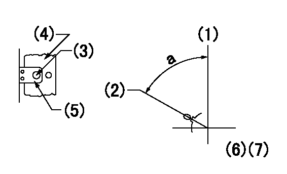
(1)Pump vertical direction
(2)Coupling's key groove position at No 1 cylinder's beginning of injection
(3)At the No 1 cylinder's beginning of injection position, stamp an aligning mark on the damper to align with the pointer's groove.
(4)Damper
(5)Pointer
(6)Pre-stroke: aa
(7)-
----------
aa=6.4+-0.03mm
----------
a=(80deg)
----------
aa=6.4+-0.03mm
----------
a=(80deg)
0000001501

A:Sealing position
B:Pre-stroke actuator
1. When installing the pre-stroke actuator on the pump, first tighten the installation bolts loosely, then move the actuator fully counterclockwise (viewed from the drive side).
Temporary tightening torque: 1 - 1.5 N.m (0.1 - 0.15 kgf.m)
2. Move the actuator in the clockwise direction when viewed from the drive side, and adjust so that it becomes the adjustment point of the adjustment value. Then tighten it.
Tightening torque: 7^9 N.m (0.7^0.9 kgf.m)
3. After prestroke actuator installation adjustment, simultaneously stamp both the actuator side and housing side.
----------
----------
----------
----------
0000001701

(PWM) Pulse width modulation (%)
(R) Rack position (mm)
Rack sensor output characteristics
1. Rack limit adjustment
(1)Measure the rack position R2 for PWM a2%.
(2)Confirm that it is within the range R2 = 15+-1 mm.
(3)Measure the rack position R1 at PWM a %.
(4)Confirm that it is within the range R2 - R1 = 10+-0.1 mm.
2. Check the limp home operation.
(1)Move the switch box's limp home switch to the limp home side.
(2)Confirm rack position L1 (mm ) and L2 (mm) for PWM in the above table.
3. Check the pull down operation.
(1)Confirm that the rack position is 19 mm at PWM B%.
(2)In the conditions described in the above table, move the switch box's pull down switch to the pull down side and confirm that the rack position momentarily becomes 1 mm or less.
----------
a1=16.25% a2=72.5% L1=1--mm L2=19++mm A=5% B=95%
----------
----------
a1=16.25% a2=72.5% L1=1--mm L2=19++mm A=5% B=95%
----------
Information:
Use the following tests for troubleshooting and repair steps. Use the ""Test for Cylinder Cutout"" in order to determine if the replacement of individual injectors is needed. Replace suspect injectors with the part number of the original injector. Use the ""Test for Leakage from Poppet Valve"" in order to determine if the full set of injectors need to be replaced. For replacement of the full set of injectors, use the current injectors and new software that is listed in Table 2.Test for Cylinder Cutout
The cylinder cutout test should be used in order to determine if an individual injector may have caused the failure.
Warm the engine out of cold mode.
Connect Cat ET to the engine while the engine is running.
Ensure that the engine speed is 1200 rpm 125 rpm. An extremely rough running engine will need to be diagnosed by other methods.
Cut out one bank of cylinders. Note engine rpm and the fuel position on the Cat ET screen at that time.
Cut out one of the remaining cylinders from the cylinder bank that is running. Allow the engine to stabilize, and note the fuel position.
Give power back to that cylinder. Allow the engine to stabilize. Note the fuel position.
Repeat steps 5 through 6 until the cylinder bank has been completely checked.
Power all cylinders. Allow the engine to stabilize.
Cut out the other cylinder bank and repeat steps 5 through 8.
Repeat steps 4 through 9 with the engine at 2000 rpm.
Compare the results from the fuel position from each cylinder.
If the cylinder was cut out and the fuel position did not change the cylinder may not have been producing power. This cylinder would be suspect.
When you are finished with the test, reduce engine RPM to low idle. Shut off the engine.
Replace any suspect injector with a similar original injector. Install new seals for the injector and the jumper tube during this repair. The repair procedure for the injector is found in Special Instruction, REHS0116.It is possible that multiple injectors are functioning improperly. Complete ""Test for Leakage from Poppet Valve"" in order to evaluate possible excessive leakage from the injectors.Test for Leakage from Poppet Valve
Warm the engine out of Cold Mode to normal operating temperature.
Turn off the engine.
Remove the valve cover bolts in preparation in order to observe the injectors. Leave the covers in place.
Hot oil and components can cause personal injury.Do not allow hot oil or components to contact skin.
Restart the engine and run at low idle with no load.
Use Cat ET in order to perform the test that overrides the injection actuation system. Increase injection actuation pressure to the maximum value.
Observe all of the injectors under each valve cover for leakage at the spill port. A small amount of dripping is acceptable. However, a continuous stream of oil is an indication of excessive leakage of the poppet valve. Only leaks at the spill port are an indication of excessive leakage from the poppet valve.
If multiple injectors display excessive leakage from the poppet valves, update the set of injectors with