Information injection-pump assembly
ZEXEL
108822-3270
1088223270

Rating:
Cross reference number
ZEXEL
108822-3270
1088223270
Zexel num
Bosch num
Firm num
Name
108822-3270
INJECTION-PUMP ASSEMBLY
Calibration Data:
Adjustment conditions
Test oil
1404 Test oil ISO4113 or {SAEJ967d}
1404 Test oil ISO4113 or {SAEJ967d}
Test oil temperature
degC
40
40
45
Nozzle and nozzle holder
105780-8250
Bosch type code
1 688 901 101
Nozzle
105780-0120
Bosch type code
1 688 901 990
Nozzle holder
105780-2190
Opening pressure
MPa
20.7
Opening pressure
kgf/cm2
211
Injection pipe
Outer diameter - inner diameter - length (mm) mm 8-3-600
Outer diameter - inner diameter - length (mm) mm 8-3-600
Overflow valve
134424-4120
Overflow valve opening pressure
kPa
255
221
289
Overflow valve opening pressure
kgf/cm2
2.6
2.25
2.95
Tester oil delivery pressure
kPa
255
255
255
Tester oil delivery pressure
kgf/cm2
2.6
2.6
2.6
PS/ACT control unit part no.
407980-2
24*
Digi switch no.
41
Direction of rotation (viewed from drive side)
Right R
Right R
Injection timing adjustment
Direction of rotation (viewed from drive side)
Right R
Right R
Injection order
1-8-6-2-
7-5-4-3
Pre-stroke
mm
7.2
7.17
7.23
Beginning of injection position
Drive side NO.1
Drive side NO.1
Difference between angles 1
Cal 1-8 deg. 45 44.75 45.25
Cal 1-8 deg. 45 44.75 45.25
Difference between angles 2
Cal 1-6 deg. 90 89.75 90.25
Cal 1-6 deg. 90 89.75 90.25
Difference between angles 3
Cyl.1-2 deg. 135 134.75 135.25
Cyl.1-2 deg. 135 134.75 135.25
Difference between angles 4
Cal 1-7 deg. 180 179.75 180.25
Cal 1-7 deg. 180 179.75 180.25
Difference between angles 5
Cal 1-5 deg. 225 224.75 225.25
Cal 1-5 deg. 225 224.75 225.25
Difference between angles 6
Cal 1-4 deg. 270 269.75 270.25
Cal 1-4 deg. 270 269.75 270.25
Difference between angles 7
Cal 1-3 deg. 315 314.75 315.25
Cal 1-3 deg. 315 314.75 315.25
Injection quantity adjustment
Adjusting point
-
Rack position
13.9
Pump speed
r/min
700
700
700
Average injection quantity
mm3/st.
148
145
151
Max. variation between cylinders
%
0
-3
3
Basic
*
Fixing the rack
*
PS407980-224*
V
2.2+-0.0
1
PS407980-224*
mm
4.8+-0.0
5
Standard for adjustment of the maximum variation between cylinders
*
Injection quantity adjustment_02
Adjusting point
Z
Rack position
7.9+-0.5
Pump speed
r/min
375
375
375
Average injection quantity
mm3/st.
14.3
13.3
15.3
Max. variation between cylinders
%
0
-10
10
Fixing the rack
*
PS407980-224*
V
V1+0.05+
-0.01
PS407980-224*
mm
7.1+-0.0
3
Standard for adjustment of the maximum variation between cylinders
*
Remarks
Refer to items regarding the pre-stroke actuator
Refer to items regarding the pre-stroke actuator
Injection quantity adjustment_03
Adjusting point
A
Rack position
R1(13.9)
Pump speed
r/min
700
700
700
Average injection quantity
mm3/st.
148
146
150
Basic
*
Fixing the lever
*
PS407980-224*
V
2.2+-0.0
1
PS407980-224*
mm
4.8+-0.0
5
Injection quantity adjustment_04
Adjusting point
B
Rack position
R1+0.95
Pump speed
r/min
1100
1100
1100
Average injection quantity
mm3/st.
136
130
142
Fixing the lever
*
PS407980-224*
V
2.2+-0.0
1
PS407980-224*
mm
4.8+-0.0
5
0000001601
Pre-stroke
mm
7.2
7.17
7.23
Remarks
When the timing sleeve is pushed up
When the timing sleeve is pushed up
_02
Connector angle
deg.
8.5
8
9
Remarks
When the eccentric pin is tightened
When the eccentric pin is tightened
_03
Supply voltage
V
24
23.5
24.5
Ambient temperature
degC
23
18
28
Pre-stroke
mm
3.2
3.15
3.25
Output voltage
V
2.95
2.94
2.96
Adjustment
*
_04
Supply voltage
V
24
23.5
24.5
Ambient temperature
degC
23
18
28
Pre-stroke
mm
7.2
7.17
7.23
Output voltage
V
1.2
1
1.4
Confirmation
*
Remarks
Output voltage V1
Output voltage V1
_05
Supply voltage
V
24
23.5
24.5
Ambient temperature
degC
23
18
28
Output voltage
V
3.05
3.05
Confirmation of operating range
*
Test data Ex:
Governor adjustment
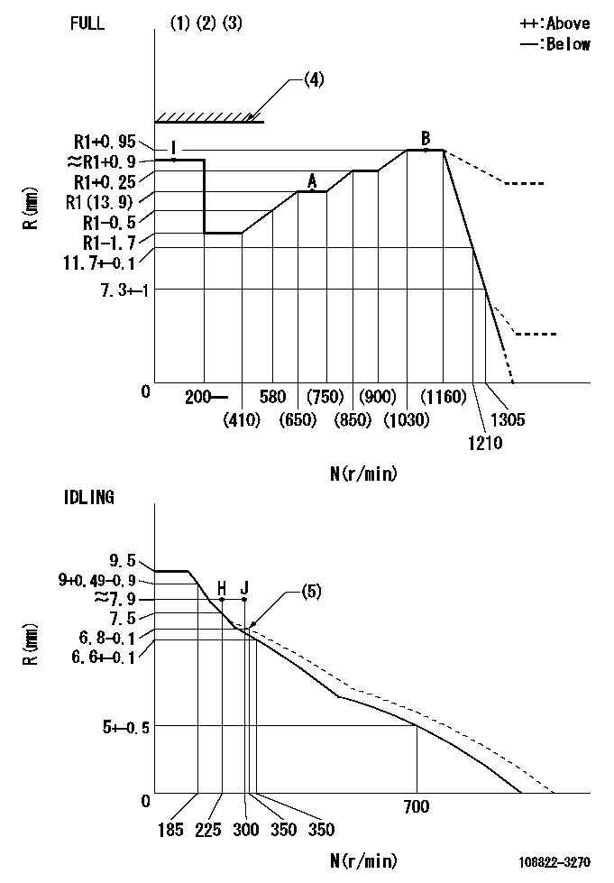
N:Pump speed
R:Rack position (mm)
(1)Torque cam stamping: T1
(2)Tolerance for racks not indicated: +-0.05mm.
(3)Set stop lever before governor adjustment. [When setting stop lever after governor adjustment, confirm that point B (Ra) can be obtained at full setting.]
(4)Stop lever's normal position setting: equivalent to RA
(5)Damper spring setting
----------
T1=AD11 Ra=R1+0.95mm RA=(17)mm
----------
----------
T1=AD11 Ra=R1+0.95mm RA=(17)mm
----------
Speed control lever angle
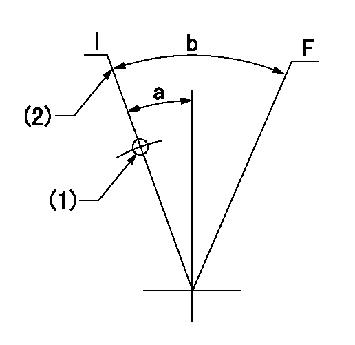
F:Full speed
I:Idle
(1)Use the hole at R = aa
(2)Stopper bolt set position 'H'
----------
aa=88mm
----------
a=12deg+-5deg b=(35.5deg)+-3deg
----------
aa=88mm
----------
a=12deg+-5deg b=(35.5deg)+-3deg
Stop lever angle
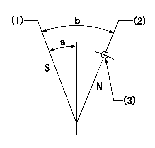
N:Pump normal
S:Stop the pump.
(1)Set the stopper bolt at rack position = aa (speed = bb)
(2)Set the stopper bolt at rack position = cc (speed = dd).
(3)At pin above R = ee
----------
aa=0.5+-0.3mm bb=0r/min cc=(17)mm dd=0r/min ee=35mm
----------
a=15deg+-5deg b=35deg+-5deg
----------
aa=0.5+-0.3mm bb=0r/min cc=(17)mm dd=0r/min ee=35mm
----------
a=15deg+-5deg b=35deg+-5deg
0000001301
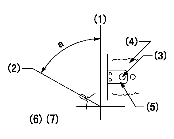
(1)Pump vertical direction
(2)Coupling's key groove position at No 1 cylinder's beginning of injection
(3)At the No 1 cylinder's beginning of injection position, stamp an aligning mark on the damper to align with the pointer's groove.
(4)Damper
(5)Pointer
(6)Pre-stroke: aa
(7)-
----------
aa=7.2+-0.03mm
----------
a=(80deg)
----------
aa=7.2+-0.03mm
----------
a=(80deg)
0000001901

A:Sealing position
B:Pre-stroke actuator
1. When installing the pre-stroke actuator on the pump, first tighten the installation bolts loosely, then move the actuator fully counterclockwise (viewed from the drive side).
Temporary tightening torque: 1 - 1.5 N.m (0.1 - 0.15 kgf.m)
2. Move the actuator in the clockwise direction when viewed from the drive side, and adjust so that it becomes the adjustment point of the adjustment value. Then tighten it.
Tightening torque: 7^9 N.m (0.7^0.9 kgf.m)
3. After prestroke actuator installation adjustment, simultaneously stamp both the actuator side and housing side.
----------
----------
----------
----------
0000002201 RACK SENSOR

(VR) measurement voltage
(I) Part number of the control unit
(G) Apply red paint.
(H): End surface of the pump
1. Rack sensor adjustment (-0620)
(1)Fix the speed control lever at the full position
(2)Set the speed to N1 r/min.
(If the boost compensator is provided, apply boost pressure.)
(3)Adjust the bobbin (A) so that the rack sensor's output voltage is VR+-0.01.
(4)At that time, rack position must be Ra.
(5)Apply G at two places.
Connecting part between the joint (B) and the nut (F)
Connecting part between the joint (B) and the end surface of the pump (H)
----------
N1=1100r/min Ra=R1(13.9)+0.95mm
----------
----------
N1=1100r/min Ra=R1(13.9)+0.95mm
----------
0000002301 AIR CYLINDER
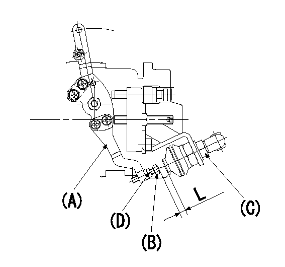
(A): Speed lever
(B): Adjusting bolt
(C): Air cylinder
(D): Locknut
Within the speed lever's operating range, temporarily tighten the adjusting bolt so that the air cylinder adjusting bolt does not contact the air cylinder (clearance L). (Air cylinder adjustment not necessary.)
----------
----------
----------
----------
Information:
The DATA SET screen ID (2) for the correct group will be listed to the right of Line 011 FUEL INJECT PUMP BENCH TEST SPEC NUM (3). Write this number DMXXXX-XX down and proceed to Section ""Displaying the DATA SET Screen When the DATA SET ID Number is Not Known"".Certain pump and governor groups will have multiple DATA SETS. Change in pump design will be tracked by pump serial number. Figure 22 is an example of a serial l number break in the data (1). The original DATA SET DMXXXX number is kept (2) but the new DATA SET has a different change level (3).
Illustration 22 g02797952
Note: Soon you will be able to use the tab key to place the cursor in front of this line. Type an X to select, Figure 21 (4). Press the enter key. The data will be displayed automatically. For now though the data will have to be displayed manually. Figure 23 (1)
Illustration 23 g02797956
Press the pf3 key to return to the ACF2 screen (2) .Proceed to Section ""Displaying the DATA SET Screen When the DATA SET ID Number is Not Known"".Displaying the DATA SET Screen When the DATA SET ID Number is Not Known
At the ACF2/IMS ONLINE MENU SYSTEM screen (1) (TMI 1.04) press the enter key (2). Figure 24
Illustration 24 g02797958
This will display the ACF2/IMS APPLICATION SELECTION MENU. Figure 25 (1) (TMI 1.05)
Illustration 25 g02797959
Use the tab key to place the cursor in front of the line GKN402 TMI - ENGINE AND COMP PERF, type an X to select (2) or type GKN402 at the APPLICATION SELECTION NO. _. (3) Press the enter key. This will display the ACF2/IMS PROGRAM SELECTION MENU screen. Figure 26 (1)
Illustration 26 g02797960
Use the tab key to place the cursor in front of line 03 and type an X to select (2) or type 03 at the PROGRAM SELECTION NO _ (3). Press the enter key. This will display the PERFORMANCE PARAMETERS INQUIRY screen. Figure 27 (1) (TMI 3.03 p1)
Illustration 27 g02797962
Type the appropriate numbers in the DATA REFERENCE NUMBER and CHANGE LEVEL fields (2). Press the enter key. The data set will be displayed on the next screen. Figure 28 (TMI 3.03)
Illustration 28 g02797963
Press the pf3 key to return to the ACF2 screen (1) .Interpreting the Specification Data Set Screens
The following screen contains flow specifications and physical parameters necessary to evaluate a fuel injection pump. Additional parameters such as calibration fluid temperatures and pressures are listed in the manual for the test bench. See Special Instruction, SEHS8200. These screens still apply to this data. Every data set (DMXXXX screen) contains data for many injection pump and governor group part numbers. The data is sorted by the profile or geometry of the basic cam and the lowest level part number of the plunger and barrel group. Most part numbers with the same basic cam, plunger, and barrel groups use the same data.Pages of data in the DATA SETS are arranged in descending pump rpm. Five or six rpm choices are listed. When the
Have questions with 108822-3270?
Group cross 108822-3270 ZEXEL
108822-3270
INJECTION-PUMP ASSEMBLY