Information injection-pump assembly
BOSCH
F 01G 09U 0H0
f01g09u0h0
ZEXEL
108822-3225
1088223225
HINO
220009995A
220009995a
Rating:
Service parts 108822-3225 INJECTION-PUMP ASSEMBLY:
1.
_
5.
AUTOM. ADVANCE MECHANIS
7.
COUPLING PLATE
11.
Nozzle and Holder
23600-3040A
12.
Open Pre:MPa(Kqf/cm2)
14.7{150}/21.6{220}
14.
NOZZLE
Include in #1:
108822-3225
as INJECTION-PUMP ASSEMBLY
Cross reference number
BOSCH
F 01G 09U 0H0
f01g09u0h0
ZEXEL
108822-3225
1088223225
HINO
220009995A
220009995a
Zexel num
Bosch num
Firm num
Name
Calibration Data:
Adjustment conditions
Test oil
1404 Test oil ISO4113 or {SAEJ967d}
1404 Test oil ISO4113 or {SAEJ967d}
Test oil temperature
degC
40
40
45
Nozzle and nozzle holder
105780-8250
Bosch type code
1 688 901 101
Nozzle
105780-0120
Bosch type code
1 688 901 990
Nozzle holder
105780-2190
Opening pressure
MPa
20.7
Opening pressure
kgf/cm2
211
Injection pipe
Outer diameter - inner diameter - length (mm) mm 8-3-600
Outer diameter - inner diameter - length (mm) mm 8-3-600
Overflow valve
134424-4120
Overflow valve opening pressure
kPa
255
221
289
Overflow valve opening pressure
kgf/cm2
2.6
2.25
2.95
Tester oil delivery pressure
kPa
255
255
255
Tester oil delivery pressure
kgf/cm2
2.6
2.6
2.6
RED3 control unit part number
407910-3
960
RED3 rack sensor specifications
mm
19
PS/ACT control unit part no.
407980-2
24*
Digi switch no.
41
Direction of rotation (viewed from drive side)
Right R
Right R
Injection timing adjustment
Direction of rotation (viewed from drive side)
Right R
Right R
Injection order
1-8-6-2-
7-5-4-3
Pre-stroke
mm
7.2
7.17
7.23
Beginning of injection position
Drive side NO.1
Drive side NO.1
Difference between angles 1
Cal 1-8 deg. 45 44.75 45.25
Cal 1-8 deg. 45 44.75 45.25
Difference between angles 2
Cal 1-6 deg. 90 89.75 90.25
Cal 1-6 deg. 90 89.75 90.25
Difference between angles 3
Cyl.1-2 deg. 135 134.75 135.25
Cyl.1-2 deg. 135 134.75 135.25
Difference between angles 4
Cal 1-7 deg. 180 179.75 180.25
Cal 1-7 deg. 180 179.75 180.25
Difference between angles 5
Cal 1-5 deg. 225 224.75 225.25
Cal 1-5 deg. 225 224.75 225.25
Difference between angles 6
Cal 1-4 deg. 270 269.75 270.25
Cal 1-4 deg. 270 269.75 270.25
Difference between angles 7
Cal 1-3 deg. 315 314.75 315.25
Cal 1-3 deg. 315 314.75 315.25
Injection quantity adjustment
Rack position
(12.5)
Vist
V
1.97
1.97
1.97
Pump speed
r/min
700
700
700
Average injection quantity
mm3/st.
148
146
150
Max. variation between cylinders
%
0
-3
3
Basic
*
PS407980-224*
V
2.2+-0.0
1
PS407980-224*
mm
4.8+-0.0
5
Injection quantity adjustment_02
Rack position
(6.3)
Vist
V
2.9
2.8
3
Pump speed
r/min
375
375
375
Average injection quantity
mm3/st.
14.3
13.3
15.3
Max. variation between cylinders
%
0
-10
10
PS407980-224*
V
V1+0.05+
-0.01
PS407980-224*
mm
7.1+-0.0
3
Remarks
Refer to items regarding the pre-stroke actuator
Refer to items regarding the pre-stroke actuator
0000001201
Pre-stroke
mm
7.2
7.17
7.23
Remarks
When the timing sleeve is pushed up
When the timing sleeve is pushed up
_02
Connector angle
deg.
11.5
11
12
Remarks
When the eccentric pin is tightened
When the eccentric pin is tightened
_03
Supply voltage
V
24
23.5
24.5
Ambient temperature
degC
23
18
28
Pre-stroke
mm
3.2
3.15
3.25
Output voltage
V
2.95
2.94
2.96
Adjustment
*
_04
Supply voltage
V
24
23.5
24.5
Ambient temperature
degC
23
18
28
Pre-stroke
mm
7.2
7.17
7.23
Output voltage
V
1.2
1
1.4
Confirmation
*
Remarks
Output voltage V1
Output voltage V1
_05
Supply voltage
V
24
23.5
24.5
Ambient temperature
degC
23
18
28
Output voltage
V
3.05
3.05
Confirmation of operating range
*
Test data Ex:
Speed control lever angle

N:Pump normal
S:Stop the pump.
(1)Rack position = aa
(2)Rack position bb
----------
aa=20mm bb=1mm
----------
a=37deg+-5deg b=2.5deg+-5deg
----------
aa=20mm bb=1mm
----------
a=37deg+-5deg b=2.5deg+-5deg
0000000901
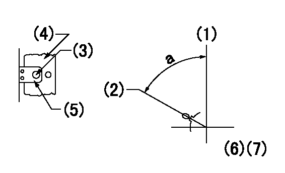
(1)Pump vertical direction
(2)Coupling's key groove position at No 1 cylinder's beginning of injection
(3)At the No 1 cylinder's beginning of injection position, stamp an aligning mark on the damper to align with the pointer's groove.
(4)Damper
(5)Pointer
(6)B.T.D.C.:-
(7)Pre-stroke: aa
----------
aa=7.2+-0.03mm
----------
a=(80deg)
----------
aa=7.2+-0.03mm
----------
a=(80deg)
0000001501

A:Sealing position
B:Pre-stroke actuator
1. When installing the pre-stroke actuator on the pump, first tighten the installation bolts loosely, then move the actuator fully counterclockwise (viewed from the drive side).
Temporary tightening torque: 1 - 1.5 N.m (0.1 - 0.15 kgf.m)
2. Move the actuator in the clockwise direction when viewed from the drive side, and adjust so that it becomes the adjustment point of the adjustment value. Then tighten it.
Tightening torque: 7^9 N.m (0.7^0.9 kgf.m)
3. After prestroke actuator installation adjustment, simultaneously stamp both the actuator side and housing side.
----------
----------
----------
----------
0000001701

(Rs) rack sensor specifications
(C/U) control unit part number
(V) Rack sensor output voltage
(R) Rack position (mm)
1. Confirming governor output characteristics (rack 19 mm, span 6 mm)
(1)When the output voltages of the rack sensor are V1 and V2, check that the rack positions R1 and R2 in the table above are satisfied.
----------
----------
----------
----------
Information:
Parts Location
Illustration 2 g01663154
Exploded view (1) 304-1108 Diesel Particulate Filter Gp (2) 304-1111 Bracket As (3) 253-4495 Clamp As (4) 277-4718 Clamp As (5) 8T-4121 Hard Washer (6) 8T-4196 Bolt (7) 5P-8245 Hard Washer (8) 6V-3823 Bolt (9) 3B-4508 Lockwasher (10) 6V-8149 Nut Installation Procedure
Diesel Particulate Filter Installation
Illustration 3 g01606033
Typical example (16) Exhaust pipe assembly (17) Clamp (18) 241-9265 Muffler Clamp (19) Pipe assembly (20) Bracket assembly (21) Support assembly (22) Muffler assembly (23) Hard washer (24) Bolt (25) Plate (26) Bolt (27) Hard washer (28) Plate (29) Washer (30) Bolt
Remove existing muffler assembly (22) and bracket assembly (20). Set aside exhaust pipe assembly (16), clamp (17), three hard washers (23), three bolts (24), three bolts (26), three hard washers (27), two washers (29), and two bolts (30). These parts will be reused in later steps.
Illustration 4 g01602298
Reuse three bolts (24) and three hard washers (23) that were used to secure the former bracket assembly (20) to secure the new 304-1111 Bracket As (2) to support assembly (21). Refer to Illustrations 3 and 4.
Reuse two bolts (30) and two washers (29) that were used to secure the former bracket assembly (20) to secure the new bracket assembly (2) to plate (28). Refer to Illustrations 3 and 4.
Reuse three bolts (26) and three hard washers (27) that were used to secure the former bracket assembly (20) to secure the new bracket assembly (2) to plate (25). Refer to Illustrations 3 and 4.
Illustration 5 g01602360
(3) 253-4495 Clamp As (5) 8T-4121 Hard Washer (6) 8T-4196 Bolt
Install the two new 253-4495 Clamp As (3) by using four 8T-4196 Bolts (6) and four 8T-4121 Hard Washers (5). Loosely secure these bolts so that the clamp assembly is adjustable. Refer to Illustration 5.
Illustration 6 g01602363
(1) 304-1108 Diesel Particulate Filter Gp (3) Clamp assembly (31) Inlet module tube
Install the new 304-1108 Diesel Particulate Filter Gp (1) on top of clamp assembly (3). Make sure that the inlet module tube (31) fits into pipe assembly (19). Use a new 241-9265 Muffler Clamp (11) to secure the joint.
Illustration 7 g01602273
(4) 277-4718 Clamp As (7) 5P-8245 Hard Washer (8) 6V-3823 Bolt (9) 3B-4508 Lockwasher (10) 6V-8149 Nut
Once you have the pipe assembly installed properly, tighten each bottom clamp assembly (3). Install the top 277-4718 Clamp As (4) by using four 5P-8245 Hard Washers (7) and four 6V-3823 Bolts (8). Use four 3B-4508 Lockwashers (9) and four 6V-8149 Nuts (10) on clamp assembly (3) side. Refer to Illustration 7.
Install exhaust pipe assembly (16) that you removed from the muffler assembly (22) to the outlet module tube of the DPF and secure the joint with existing clamp (17) that you removed from the muffler assembly.
Reconnect the drain lines.
Insulate pipe assembly (19) from the turbo end to the inlet