Information injection-pump assembly
BOSCH
F 01G 09U 0GR
f01g09u0gr
ZEXEL
108822-3114
1088223114
HINO
220009123A
220009123a
Rating:
Service parts 108822-3114 INJECTION-PUMP ASSEMBLY:
1.
_
5.
AUTOM. ADVANCE MECHANIS
7.
COUPLING PLATE
11.
Nozzle and Holder
23600-2750A
12.
Open Pre:MPa(Kqf/cm2)
14.7{150}/21.6{220}
14.
NOZZLE
Include in #1:
108822-3114
as INJECTION-PUMP ASSEMBLY
Cross reference number
BOSCH
F 01G 09U 0GR
f01g09u0gr
ZEXEL
108822-3114
1088223114
HINO
220009123A
220009123a
Zexel num
Bosch num
Firm num
Name
Calibration Data:
Adjustment conditions
Test oil
1404 Test oil ISO4113 or {SAEJ967d}
1404 Test oil ISO4113 or {SAEJ967d}
Test oil temperature
degC
40
40
45
Nozzle and nozzle holder
105780-8250
Bosch type code
1 688 901 101
Nozzle
105780-0120
Bosch type code
1 688 901 990
Nozzle holder
105780-2190
Opening pressure
MPa
20.7
Opening pressure
kgf/cm2
211
Injection pipe
Outer diameter - inner diameter - length (mm) mm 8-3-600
Outer diameter - inner diameter - length (mm) mm 8-3-600
Overflow valve
134424-4120
Overflow valve opening pressure
kPa
255
221
289
Overflow valve opening pressure
kgf/cm2
2.6
2.25
2.95
Tester oil delivery pressure
kPa
255
255
255
Tester oil delivery pressure
kgf/cm2
2.6
2.6
2.6
PS/ACT control unit part no.
407980-2
24*
Digi switch no.
41
Direction of rotation (viewed from drive side)
Right R
Right R
Injection timing adjustment
Direction of rotation (viewed from drive side)
Right R
Right R
Injection order
1-8-6-2-
7-5-4-3
Pre-stroke
mm
7.2
7.17
7.23
Beginning of injection position
Drive side NO.1
Drive side NO.1
Difference between angles 1
Cal 1-8 deg. 45 44.75 45.25
Cal 1-8 deg. 45 44.75 45.25
Difference between angles 2
Cal 1-6 deg. 90 89.75 90.25
Cal 1-6 deg. 90 89.75 90.25
Difference between angles 3
Cyl.1-2 deg. 135 134.75 135.25
Cyl.1-2 deg. 135 134.75 135.25
Difference between angles 4
Cal 1-7 deg. 180 179.75 180.25
Cal 1-7 deg. 180 179.75 180.25
Difference between angles 5
Cal 1-5 deg. 225 224.75 225.25
Cal 1-5 deg. 225 224.75 225.25
Difference between angles 6
Cal 1-4 deg. 270 269.75 270.25
Cal 1-4 deg. 270 269.75 270.25
Difference between angles 7
Cal 1-3 deg. 315 314.75 315.25
Cal 1-3 deg. 315 314.75 315.25
Injection quantity adjustment
Adjusting point
-
Rack position
13.9
Pump speed
r/min
700
700
700
Average injection quantity
mm3/st.
148
145
151
Max. variation between cylinders
%
0
-3
3
Basic
*
Fixing the rack
*
PS407980-224*
V
2.2+-0.0
1
PS407980-224*
mm
4.8+-0.0
5
Standard for adjustment of the maximum variation between cylinders
*
Injection quantity adjustment_02
Adjusting point
Z
Rack position
7.9+-0.5
Pump speed
r/min
375
375
375
Average injection quantity
mm3/st.
14.3
11.3
17.3
Max. variation between cylinders
%
0
-10
10
Fixing the rack
*
PS407980-224*
V
V1+0.05+
-0.01
PS407980-224*
mm
7.1+-0.0
3
Standard for adjustment of the maximum variation between cylinders
*
Remarks
Refer to items regarding the pre-stroke actuator
Refer to items regarding the pre-stroke actuator
Injection quantity adjustment_03
Adjusting point
A
Rack position
R1(13.9)
Pump speed
r/min
700
700
700
Average injection quantity
mm3/st.
148
146
150
Basic
*
Fixing the lever
*
PS407980-224*
V
2.2+-0.0
1
PS407980-224*
mm
4.8+-0.0
5
Injection quantity adjustment_04
Adjusting point
B
Rack position
R1+0.95
Pump speed
r/min
1100
1100
1100
Average injection quantity
mm3/st.
136
130
142
Fixing the lever
*
PS407980-224*
V
2.2+-0.0
1
PS407980-224*
mm
4.8+-0.0
5
0000001601
Pre-stroke
mm
7.2
7.17
7.23
Remarks
When the timing sleeve is pushed up
When the timing sleeve is pushed up
_02
Connector angle
deg.
8.5
8
9
Remarks
When the eccentric pin is tightened
When the eccentric pin is tightened
_03
Supply voltage
V
24
23.5
24.5
Ambient temperature
degC
23
18
28
Pre-stroke
mm
3.2
3.15
3.25
Output voltage
V
2.95
2.94
2.96
Adjustment
*
_04
Supply voltage
V
24
23.5
24.5
Ambient temperature
degC
23
18
28
Pre-stroke
mm
7.2
7.17
7.23
Output voltage
V
1.2
1
1.4
Confirmation
*
Remarks
Output voltage V1
Output voltage V1
_05
Supply voltage
V
24
23.5
24.5
Ambient temperature
degC
23
18
28
Output voltage
V
3.05
3.05
Confirmation of operating range
*
Test data Ex:
Governor adjustment
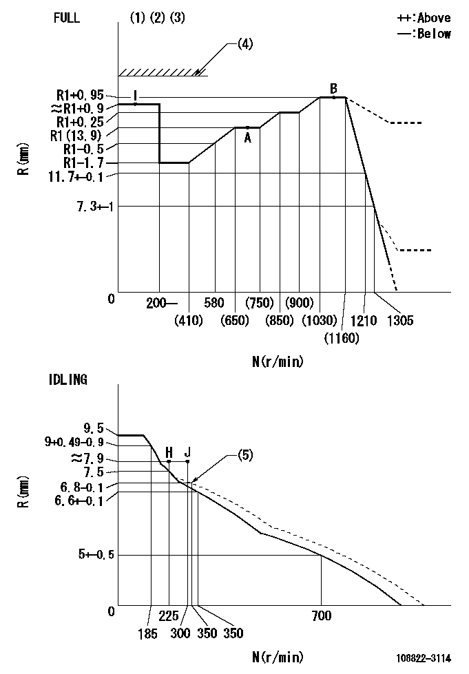
N:Pump speed
R:Rack position (mm)
(1)Torque cam stamping: T1
(2)Tolerance for racks not indicated: +-0.05mm.
(3)Set stop lever before governor adjustment. [When setting stop lever after governor adjustment, confirm that point B (Ra) can be obtained at full setting.]
(4)Stop lever's normal position setting: RA
(5)Damper spring setting
----------
T1=AD11 Ra=R1+0.95mm RA=(17)mm
----------
----------
T1=AD11 Ra=R1+0.95mm RA=(17)mm
----------
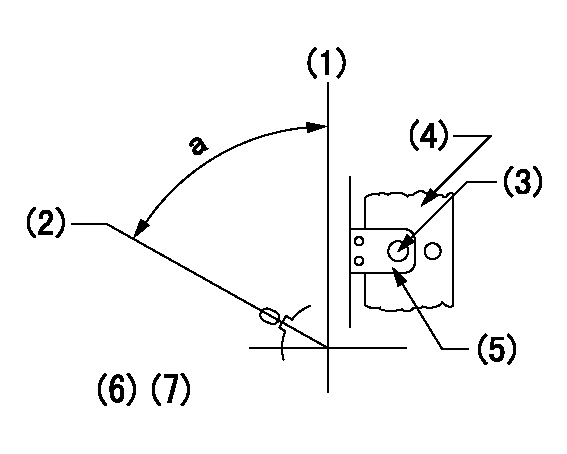
Speed control lever angle
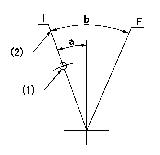
F:Full speed
I:Idle
(1)Use the hole at R = aa
(2)Stopper bolt set position 'H'
----------
aa=88mm
----------
a=12deg+-5deg b=(35.5deg)+-3deg
----------
aa=88mm
----------
a=12deg+-5deg b=(35.5deg)+-3deg
Stop lever angle
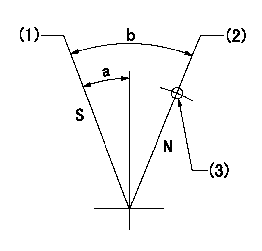
N:Pump normal
S:Stop the pump.
(1)At rack position aa, set the stopper bolt (pump speed bb r/min).
(2)Set the stopper bolt at rack position = cc (speed = dd).
(3)At pin above R = ee
----------
aa=0.5+-0.3mm bb=0r/min cc=(17)mm dd=0r/min ee=35mm
----------
a=15deg+-5deg b=35deg+-5deg
----------
aa=0.5+-0.3mm bb=0r/min cc=(17)mm dd=0r/min ee=35mm
----------
a=15deg+-5deg b=35deg+-5deg
0000001301
(1)Pump vertical direction
(2)Coupling's key groove position at No 1 cylinder's beginning of injection
(3)At the No 1 cylinder's beginning of injection position, stamp an aligning mark on the damper to align with the pointer's groove.
(4)Damper
(5)Pointer
(6)Pre-stroke: aa
(7)-
----------
aa=7.2+-0.03mm
----------
a=(80deg)
----------
aa=7.2+-0.03mm
----------
a=(80deg)
0000001901

A:Sealing position
B:Pre-stroke actuator
1. When installing the pre-stroke actuator on the pump, first tighten the installation bolts loosely, then move the actuator fully counterclockwise (viewed from the drive side).
Temporary tightening torque: 1 - 1.5 N.m (0.1 - 0.15 kgf.m)
2. Move the actuator in the clockwise direction when viewed from the drive side, and adjust so that it becomes the adjustment point of the adjustment value. Then tighten it.
Tightening torque: 7^9 N.m (0.7^0.9 kgf.m)
3. After prestroke actuator installation adjustment, simultaneously stamp both the actuator side and housing side.
----------
----------
----------
----------
0000002201 RACK SENSOR

(VR) measurement voltage
(I) Part number of the control unit
(G) Apply red paint.
(H): End surface of the pump
1. Rack sensor adjustment (-0620)
(1)Fix the speed control lever at the full position
(2)Set the speed to N1 r/min.
(If the boost compensator is provided, apply boost pressure.)
(3)Adjust the bobbin (A) so that the rack sensor's output voltage is VR+-0.01.
(4)At that time, rack position must be Ra.
(5)Apply G at two places.
Connecting part between the joint (B) and the nut (F)
Connecting part between the joint (B) and the end surface of the pump (H)
----------
N1=1100r/min Ra=R1(13.9)+0.95mm
----------
----------
N1=1100r/min Ra=R1(13.9)+0.95mm
----------
0000002301 AIR CYLINDER
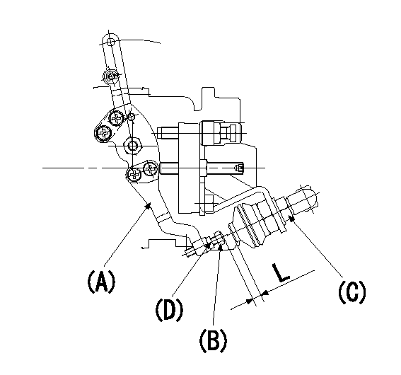
(A): Speed lever
(B): Adjusting bolt
(C): Air cylinder
(D): Locknut
Within the speed lever's operating range, temporarily tighten the adjusting bolt so that the air cylinder adjusting bolt does not contact the air cylinder (clearance L). (Air cylinder adjustment not necessary.)
----------
----------
----------
----------
Information:
Ultra Low Sulfur Diesel (ULSD) poses a greater static ignition hazard than earlier diesel formulations, with a higher sulfur content, which may result in a fire or explosion. Consult with your fuel or fuel system supplier for details on proper grounding and bonding practices.
Note: The removal of sulfur and other compounds in Ultra Low Sulfur Diesel (ULSD) fuel decreases the conductivity of ULSD and increases the ability of the fuel to store static charge. Refineries may have treated the fuel with a static dissipating additive. However, there are many factors that can reduce the effectiveness of the additive over time. Static charges can build up in ULSD fuel while the fuel is flowing through fuel delivery systems. Static electricity discharge when combustible vapors are present could result in a fire or explosion. Therefore, ensuring that the entire system used to refuel your machine (fuel supply tank, transfer pump, transfer hose, nozzle, and others) is properly grounded and bonded is important. Consult with your fuel or fuel system supplier to ensure that the delivery system is in compliance with fueling standards for proper grounding and bonding practices.The two basic types of distillate diesel fuel are No. 2 diesel fuel and No. 1 diesel fuel. No. 2 diesel fuel is the most commonly available summer grade diesel fuel. No. 1 diesel fuel is a winter grade diesel fuel. During the winter months fuel suppliers will typically blend No. 1 and No. 2 diesel fuel in various percentages to meet the historical low ambient temperature cold-flow needs for a given area or region. No. 2 diesel fuel is a heavier diesel fuel than No. 1 diesel fuel. In cold weather, heavier fuels can cause problems with fuel filters, fuel lines, fuel tanks, and fuel storage. Heavier diesel fuels such as No. 2 diesel fuel can be used in diesel engines that operate in cold temperatures with an appropriate amount of a well proven pour point depressant additive. For more information on fuels which include blends of No. 1 and No. 2 diesel fuel, consult your fuel supplier.When you use No. 2 diesel fuel or other heavier fuels, some of the fuel characteristics may interfere with successful cold-weather operation. Additional information about the characteristics of diesel fuel is available. This information contains a discussion on the modification to the characteristics of diesel fuel. There are several possible methods that can be used to compensate for the fuel qualities that may interfere with cold-weather operation. These methods include the use of starting aids, engine coolant heaters, fuel heaters, and de-icers. In addition, the manufacturer of the fuel can add cold flow improvers and/or blend No. 1 and No. 2 diesel in various percentages.Not all areas of the world classify diesel fuel using the No. 1 and No. 2 nomenclature described above. But, the basic principles of using additives and/or blending fuels of different densities to help compensate for the fuel qualities that may interfere with cold-weather operation are the same.Starting Aids
The use of