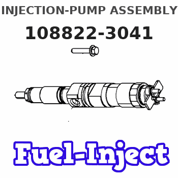
Information injection-pump assembly
ZEXEL
108822-3041
1088223041
Rating:
Service parts 108822-3041 INJECTION-PUMP ASSEMBLY:
1.
_
5.
AUTOM. ADVANCE MECHANIS
7.
COUPLING PLATE
11.
Nozzle and Holder
23600-2750A
12.
Open Pre:MPa(Kqf/cm2)
14.7{150}/21.6{220}
14.
NOZZLE
Include in #1:
108822-3041
as INJECTION-PUMP ASSEMBLY
Cross reference number
ZEXEL
108822-3041
1088223041
Zexel num
Bosch num
Firm num
Name
108822-3041
INJECTION-PUMP ASSEMBLY
Calibration Data:
Adjustment conditions
Test oil
1404 Test oil ISO4113 or {SAEJ967d}
1404 Test oil ISO4113 or {SAEJ967d}
Test oil temperature
degC
40
40
45
Nozzle and nozzle holder
105780-8250
Bosch type code
1 688 901 101
Nozzle
105780-0120
Bosch type code
1 688 901 990
Nozzle holder
105780-2190
Opening pressure
MPa
20.7
Opening pressure
kgf/cm2
211
Injection pipe
Outer diameter - inner diameter - length (mm) mm 8-3-600
Outer diameter - inner diameter - length (mm) mm 8-3-600
Overflow valve
134424-4120
Overflow valve opening pressure
kPa
255
221
289
Overflow valve opening pressure
kgf/cm2
2.6
2.25
2.95
Tester oil delivery pressure
kPa
255
255
255
Tester oil delivery pressure
kgf/cm2
2.6
2.6
2.6
PS/ACT control unit part no.
407980-2
24*
Digi switch no.
41
Direction of rotation (viewed from drive side)
Right R
Right R
Injection timing adjustment
Direction of rotation (viewed from drive side)
Right R
Right R
Injection order
1-8-6-2-
7-5-4-3
Pre-stroke
mm
7.2
7.17
7.23
Beginning of injection position
Drive side NO.1
Drive side NO.1
Difference between angles 1
Cal 1-8 deg. 45 44.75 45.25
Cal 1-8 deg. 45 44.75 45.25
Difference between angles 2
Cal 1-6 deg. 90 89.75 90.25
Cal 1-6 deg. 90 89.75 90.25
Difference between angles 3
Cyl.1-2 deg. 135 134.75 135.25
Cyl.1-2 deg. 135 134.75 135.25
Difference between angles 4
Cal 1-7 deg. 180 179.75 180.25
Cal 1-7 deg. 180 179.75 180.25
Difference between angles 5
Cal 1-5 deg. 225 224.75 225.25
Cal 1-5 deg. 225 224.75 225.25
Difference between angles 6
Cal 1-4 deg. 270 269.75 270.25
Cal 1-4 deg. 270 269.75 270.25
Difference between angles 7
Cal 1-3 deg. 315 314.75 315.25
Cal 1-3 deg. 315 314.75 315.25
Injection quantity adjustment
Adjusting point
-
Rack position
13.9
Pump speed
r/min
700
700
700
Average injection quantity
mm3/st.
148
145
151
Max. variation between cylinders
%
0
-2
2
Basic
*
Fixing the rack
*
PS407980-224*
V
2.2+-0.0
1
PS407980-224*
mm
4.8+-0.0
5
Standard for adjustment of the maximum variation between cylinders
*
Injection quantity adjustment_02
Adjusting point
Z
Rack position
7.9+-0.5
Pump speed
r/min
375
375
375
Average injection quantity
mm3/st.
14.3
11.3
17.3
Max. variation between cylinders
%
0
-15
15
Fixing the rack
*
PS407980-224*
V
V1+0.05+
-0.01
PS407980-224*
mm
7.1+-0.0
3
Standard for adjustment of the maximum variation between cylinders
*
Remarks
Refer to items regarding the pre-stroke actuator
Refer to items regarding the pre-stroke actuator
Injection quantity adjustment_03
Adjusting point
A
Rack position
R1(13.9)
Pump speed
r/min
700
700
700
Average injection quantity
mm3/st.
148
146
150
Basic
*
Fixing the lever
*
PS407980-224*
V
2.2+-0.0
1
PS407980-224*
mm
4.8+-0.0
5
Injection quantity adjustment_04
Adjusting point
B
Rack position
R1+0.95
Pump speed
r/min
1100
1100
1100
Average injection quantity
mm3/st.
136
130
142
Fixing the lever
*
PS407980-224*
V
2.2+-0.0
1
PS407980-224*
mm
4.8+-0.0
5
0000001601
Pre-stroke
mm
7.2
7.17
7.23
Remarks
When the timing sleeve is pushed up
When the timing sleeve is pushed up
_02
Connector angle
deg.
8.5
8
9
Remarks
When the eccentric pin is tightened
When the eccentric pin is tightened
_03
Supply voltage
V
24
23.5
24.5
Ambient temperature
degC
23
18
28
Pre-stroke
mm
3.2
3.15
3.25
Output voltage
V
2.95
2.94
2.96
Adjustment
*
_04
Supply voltage
V
24
23.5
24.5
Ambient temperature
degC
23
18
28
Pre-stroke
mm
7.2
7.17
7.23
Output voltage
V
1.2
1
1.4
Confirmation
*
Remarks
Output voltage V1
Output voltage V1
_05
Supply voltage
V
24
23.5
24.5
Ambient temperature
degC
23
18
28
Output voltage
V
3.05
3.05
Confirmation of operating range
*
Test data Ex:
Governor adjustment
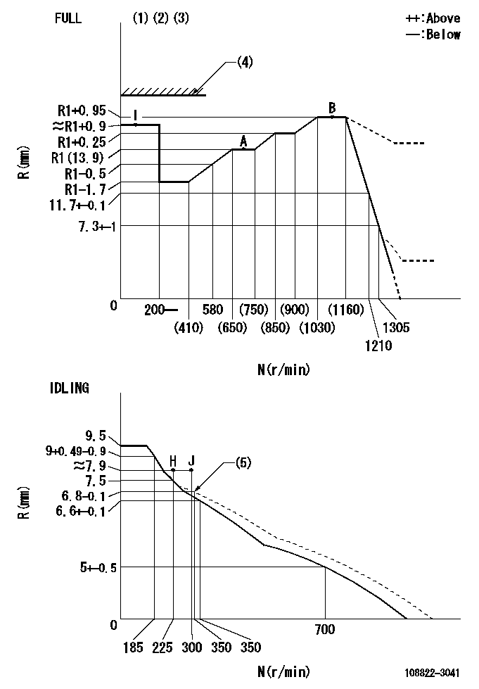
N:Pump speed
R:Rack position (mm)
(1)Torque cam stamping: T1
(2)Tolerance for racks not indicated: +-0.05mm.
(3)Set stop lever before governor adjustment. [When setting stop lever after governor adjustment, confirm that point B (Ra) can be obtained at full setting.]
(4)Stop lever's normal position setting: equivalent to RA
(5)Damper spring setting
----------
T1=AD11 Ra=R1+0.95mm RA=(17)mm
----------
----------
T1=AD11 Ra=R1+0.95mm RA=(17)mm
----------
Speed control lever angle
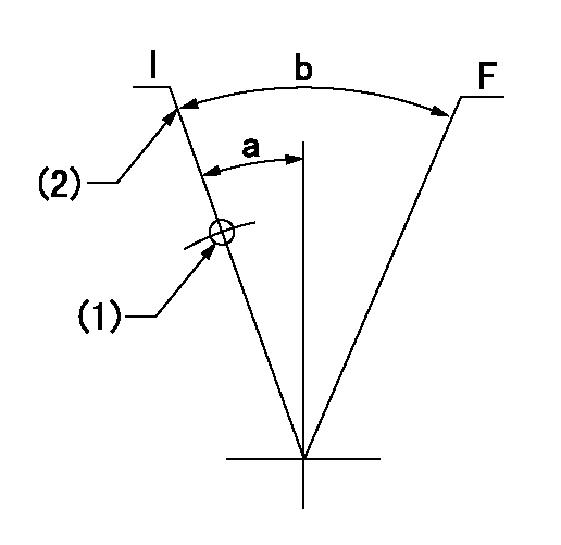
F:Full speed
I:Idle
(1)Use the hole at R = aa
(2)Stopper bolt set position 'H'
----------
aa=88mm
----------
a=10deg+-5deg b=(35.5deg)+-3deg
----------
aa=88mm
----------
a=10deg+-5deg b=(35.5deg)+-3deg
Stop lever angle
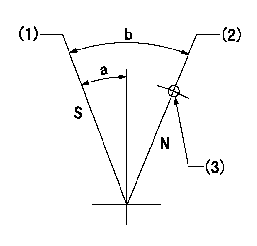
N:Pump normal
S:Stop the pump.
(1)Set the stopper bolt at rack position = aa (speed = bb)
(2)Set the stopper bolt at rack position = cc (speed = dd).
(3)At pin above R = ee
----------
aa=0.5+-0.3mm bb=0r/min cc=(17)mm dd=0r/min ee=35mm
----------
a=15deg+-5deg b=35deg+-5deg
----------
aa=0.5+-0.3mm bb=0r/min cc=(17)mm dd=0r/min ee=35mm
----------
a=15deg+-5deg b=35deg+-5deg
0000001301
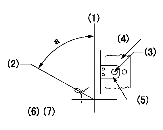
(1)Pump vertical direction
(2)Coupling's key groove position at No 1 cylinder's beginning of injection
(3)At the No 1 cylinder's beginning of injection position, stamp an aligning mark on the damper to align with the pointer's groove.
(4)Damper
(5)Pointer
(6)Pre-stroke: aa
(7)-
----------
aa=7.2+-0.03mm
----------
a=(80deg)
----------
aa=7.2+-0.03mm
----------
a=(80deg)
0000001901

A:Sealing position
B:Pre-stroke actuator
1. When installing the pre-stroke actuator on the pump, first tighten the installation bolts loosely, then move the actuator fully counterclockwise (viewed from the drive side).
Temporary tightening torque: 1 - 1.5 N.m (0.1 - 0.15 kgf.m)
2. Move the actuator in the clockwise direction when viewed from the drive side, and adjust so that it becomes the adjustment point of the adjustment value. Then tighten it.
Tightening torque: 7^9 N.m (0.7^0.9 kgf.m)
3. After prestroke actuator installation adjustment, simultaneously stamp both the actuator side and housing side.
----------
----------
----------
----------
0000002201 RACK SENSOR

(VR) measurement voltage
(I) Part number of the control unit
(G) Apply red paint.
(H): End surface of the pump
1. Rack sensor adjustment (-0620)
(1)Fix the speed control lever at the full position
(2)Set the speed to N1 r/min.
(If the boost compensator is provided, apply boost pressure.)
(3)Adjust the bobbin (A) so that the rack sensor's output voltage is VR+-0.01.
(4)At that time, rack position must be Ra.
(5)Apply G at two places.
Connecting part between the joint (B) and the nut (F)
Connecting part between the joint (B) and the end surface of the pump (H)
----------
N1=1100r/min Ra=R1(13.9)+0.95mm
----------
----------
N1=1100r/min Ra=R1(13.9)+0.95mm
----------
0000002301 AIR CYLINDER
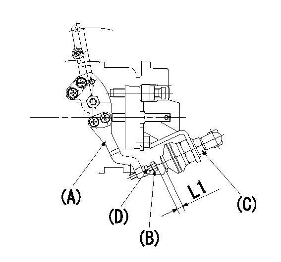
(A): Speed lever
(B): Adjusting bolt
(C): Air cylinder
(D): Locknut
Adjustment of the air cylinder
1. Set the speed lever at the idling position.
2. Set the gap between the air cylinder (a) and the set bolt (b) to L1.
3. Set speed at N1 and apply positive pressure P1 to the air cylinder (c). Read the rack position value at the same speed.
4. Slowly push the set bolt (b) out and fix it using the nut (d) when the rack position is R1 at N1.
5. Apply positive pressure several times and confirm that the lever returns to the idle position at positive pressure P2.
6. Also, at positive pressure P1confirm that the rack position is R1 and complete adjustment.
----------
L1=(6)mm R1=7.5+-0.1mm N1=325r/min P1=392+98kPa(4+1kgf/cm2) P2=0kPa(0kgf/cm2)
----------
----------
L1=(6)mm R1=7.5+-0.1mm N1=325r/min P1=392+98kPa(4+1kgf/cm2) P2=0kPa(0kgf/cm2)
----------
Information:
PARTS NEEDED
Qty
Part Number Description
4 8T2223 BOLT-SOCKET HD
1 8T9524 SEAL-O-RING
1 20R5566 INJECTOR GP-FUEL
1 2287089 SEAL-O-RING-ORFS
1 2287100 SEAL-O-RING-STOR
1 2287108 SEAL-O-RING-STOR
1 2300940 SEAL-PIP
1 2697852 SEAL-O-RING
1 3170808 SEAL-O-RING
In order to allow equitable parts availability to all participating dealers, please limit your initial parts order to not exceed 1% of dealership population. This is an initial order recommendation only, and the ultimate responsibility for ordering the total number of parts needed to satisfy the program lies with the dealer.
ACTION REQUIRED
Perform a Fuel Status Verification Test (FSVT). Follow all procedures outlined in KENR5398.
Replace injectors showing INJ-2, INJ-7 or INJ-12 codes. Schedule the replacement in line with the 1500 hour recommendation described in KENR5398.
Refer to KENR6052 for removal and installation instructions.
To qualify for this program:
Machine must be operating the most current software release in SIS Web.
Machine must be operating with the Clean Fuel Module (CFM) installed and activated.
Attach a Product Status Report to the claim form.
Provide injector replacement tracking sheet copy for specific machine SN on claim.
Conduct a review of the maintenance history of the machine to ensure no High Pressure Fuel Pump failure occurred within 250 service hours of an injector failure. If a high pressure fuel pump has failed, inspect the 2D inline filter for damage and/or debris.
Must have fuel samples from month of failure with passing (green/no action suggested) fuel quality report. Program Administrator will audit if fuel sample program is being executed per agreement.
Failure to provide the requested information and/or the failed injector could result in a claim being debited or rejected.
SERVICE CLAIM ALLOWANCES
Product smu/age whichever comes first Caterpillar Dealer Suggested Customer Suggested
Parts % Labor Hrs% Parts % Labor Hrs% Parts % Labor Hrs%
0-6000 hrs,
0-12 mo 100.0% 100.0% 0.0% 0.0% 0.0% 0.0%
6001-12000 hrs,
13-24 mo 100.0% 50.0% 0.0% 0.0% 0.0% 50.0%
This is a 2.0-hour job
If there has been a previous repair, part age/hours will apply. Retain a copy of the previous repair invoice in the dealer's records for audit purposes, and specify repair date and machine hours in the "Additional Comments" section of the warranty claim.
PARTS DISPOSITION
Hold all fuel injectors for a Parts Return Request (PRR). A Parts Return Request (PRR) will be issued to you through the Send-It-Back process after the claim is submitted. Make sure to list the service letter program number on the packing slip and include the closed work order paperwork. Handle all other parts in accordance with your Warranty Bulletin on warranty parts handling.
If a Parts Return Request (PRR) is not issued to you after 30 days through the Send-It-Back process, handle the parts in accordance with your warranty bulletin on warranty parts handling.
Have questions with 108822-3041?
Group cross 108822-3041 ZEXEL
108822-3041
INJECTION-PUMP ASSEMBLY