Information injection-pump assembly
ZEXEL
108822-3000
1088223000
HINO
220008100A
220008100a

Rating:
Cross reference number
ZEXEL
108822-3000
1088223000
HINO
220008100A
220008100a
Zexel num
Bosch num
Firm num
Name
Calibration Data:
Adjustment conditions
Test oil
1404 Test oil ISO4113 or {SAEJ967d}
1404 Test oil ISO4113 or {SAEJ967d}
Test oil temperature
degC
40
40
45
Nozzle and nozzle holder
105780-8140
Bosch type code
EF8511/9A
Nozzle
105780-0000
Bosch type code
DN12SD12T
Nozzle holder
105780-2080
Bosch type code
EF8511/9
Opening pressure
MPa
17.2
Opening pressure
kgf/cm2
175
Injection pipe
Outer diameter - inner diameter - length (mm) mm 8-3-600
Outer diameter - inner diameter - length (mm) mm 8-3-600
Overflow valve
134424-0820
Overflow valve opening pressure
kPa
127
107
147
Overflow valve opening pressure
kgf/cm2
1.3
1.1
1.5
Tester oil delivery pressure
kPa
157
157
157
Tester oil delivery pressure
kgf/cm2
1.6
1.6
1.6
PS/ACT control unit part no.
407980-2
24*
Digi switch no.
42
Direction of rotation (viewed from drive side)
Right R
Right R
Injection timing adjustment
Direction of rotation (viewed from drive side)
Right R
Right R
Injection order
1-8-6-2-
7-5-4-3
Pre-stroke
mm
6.4
6.37
6.43
Beginning of injection position
Drive side NO.1
Drive side NO.1
Difference between angles 1
Cal 1-8 deg. 45 44.75 45.25
Cal 1-8 deg. 45 44.75 45.25
Difference between angles 2
Cal 1-6 deg. 90 89.75 90.25
Cal 1-6 deg. 90 89.75 90.25
Difference between angles 3
Cyl.1-2 deg. 135 134.75 135.25
Cyl.1-2 deg. 135 134.75 135.25
Difference between angles 4
Cal 1-7 deg. 180 179.75 180.25
Cal 1-7 deg. 180 179.75 180.25
Difference between angles 5
Cal 1-5 deg. 225 224.75 225.25
Cal 1-5 deg. 225 224.75 225.25
Difference between angles 6
Cal 1-4 deg. 270 269.75 270.25
Cal 1-4 deg. 270 269.75 270.25
Difference between angles 7
Cal 1-3 deg. 315 314.75 315.25
Cal 1-3 deg. 315 314.75 315.25
Injection quantity adjustment
Adjusting point
A
Rack position
10.7
Pump speed
r/min
700
700
700
Average injection quantity
mm3/st.
210
208
212
Max. variation between cylinders
%
0
-2
2
Basic
*
Fixing the lever
*
Boost pressure
kPa
46.7
46.7
Boost pressure
mmHg
350
350
PS407980-224*
V
2.45+-0.
01
PS407980-224*
mm
4+-0.05
Injection quantity adjustment_02
Adjusting point
B
Rack position
10.1
Pump speed
r/min
500
500
500
Average injection quantity
mm3/st.
205
202
208
Fixing the lever
*
Boost pressure
kPa
46.7
46.7
Boost pressure
mmHg
350
350
PS407980-224*
V
2.45+-0.
01
PS407980-224*
mm
4+-0.05
Injection quantity adjustment_03
Adjusting point
C
Rack position
10.7+-0.
5
Pump speed
r/min
1100
1100
1100
Average injection quantity
mm3/st.
212
209
215
Fixing the lever
*
Boost pressure
kPa
46.7
46.7
Boost pressure
mmHg
350
350
PS407980-224*
V
2.45+-0.
01
PS407980-224*
mm
4+-0.05
Injection quantity adjustment_04
Adjusting point
F
Rack position
-
Pump speed
r/min
100
100
100
Average injection quantity
mm3/st.
120
120
Fixing the lever
*
Boost pressure
kPa
0
0
0
Boost pressure
mmHg
0
0
0
PS407980-224*
V
2.45+-0.
01
PS407980-224*
mm
4+-0.05
Injection quantity adjustment_05
Adjusting point
G
Rack position
4.4+-0.5
Pump speed
r/min
225
225
225
Average injection quantity
mm3/st.
10
7
13
Max. variation between cylinders
%
0
-15
15
Fixing the lever
*
Boost pressure
kPa
0
0
0
Boost pressure
mmHg
0
0
0
PS407980-224*
V
V1+0.05+
-0.01
PS407980-224*
mm
6.3+-0.0
3
Remarks
Refer to items regarding the pre-stroke actuator
Refer to items regarding the pre-stroke actuator
Injection quantity adjustment_06
Adjusting point
H
Rack position
-
Pump speed
r/min
300
300
300
Average injection quantity
mm3/st.
256
251
261
Fixing the lever
*
Boost pressure
kPa
46.7
46.7
Boost pressure
mmHg
350
350
Rack limit
*
PS407980-224*
V
2.45+-0.
01
PS407980-224*
mm
4+-0.05
Boost compensator adjustment
Pump speed
r/min
500
500
500
Rack position
7.9
Boost pressure
kPa
7.3
6
8.6
Boost pressure
mmHg
55
45
65
Boost compensator adjustment_02
Pump speed
r/min
500
500
500
Rack position
10.1
Boost pressure
kPa
33.3
33.3
33.3
Boost pressure
mmHg
250
250
250
0000001601
Pre-stroke
mm
6.4
6.37
6.43
Remarks
When the timing sleeve is pushed up
When the timing sleeve is pushed up
_02
Connector angle
deg.
8.5
8
9
Remarks
When the eccentric pin is tightened
When the eccentric pin is tightened
_03
Supply voltage
V
24
23.5
24.5
Ambient temperature
degC
23
18
28
Pre-stroke
mm
4
3.95
4.05
Output voltage
V
2.45
2.44
2.46
Adjustment
*
_04
Supply voltage
V
24
23.5
24.5
Ambient temperature
degC
23
18
28
Pre-stroke
mm
6.4
6.37
6.43
Output voltage
V
1.2
1
1.4
Confirmation
*
Remarks
Output voltage V1
Output voltage V1
_05
Supply voltage
V
24
23.5
24.5
Ambient temperature
degC
23
18
28
Pre-stroke
mm
3.4
Output voltage
V
3
2.98
3
Confirmation
*
_06
Supply voltage
V
24
23.5
24.5
Ambient temperature
degC
23
18
28
Output voltage
V
3.05
3.05
Confirmation of operating range
*
Test data Ex:
Governor adjustment
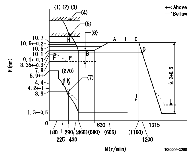
N:Pump speed
R:Rack position (mm)
(1)Tolerance for racks not indicated: +-0.05mm.
(2)Set idle at point K (N = N1, R = R1) and confirm that the injection quantity does not exceed Q1 at point J (N = N2). The pre-stroke at that time must be Pr1 (Pv1).
(3)Supplied with torque spring not set.
(4)Stop lever setting: R2
(5)RACK LIMIT
(6)Boost compensator stroke: BCL
(7)Damper spring setting
----------
N1=300r/min R1=4.4mm N2=1100r/min Q1=5mm3/st Pr1=4+-0.05mm Pv1=2.45+-0.01V R2=(14)+0.5mm BCL=2.2+-0.1mm
----------
----------
N1=300r/min R1=4.4mm N2=1100r/min Q1=5mm3/st Pr1=4+-0.05mm Pv1=2.45+-0.01V R2=(14)+0.5mm BCL=2.2+-0.1mm
----------
Speed control lever angle
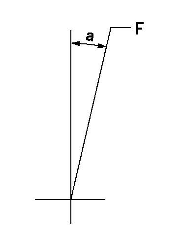
F:Full speed
----------
----------
a=18.5deg+-5deg
----------
----------
a=18.5deg+-5deg
0000000901
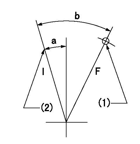
F:Full load
I:Idle
(1)Use the hole at R = aa
(2)Stopper bolt setting
----------
aa=79mm
----------
a=24deg+-5deg b=32deg+-3deg
----------
aa=79mm
----------
a=24deg+-5deg b=32deg+-3deg
Stop lever angle
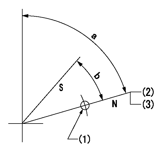
N:Pump normal
S:Stop the pump.
(1)Use the pin at R = aa
(2)Rack position bb
(3)Set the stopper screw. (After setting, apply red paint.)
----------
aa=27.5mm bb=(14)+0.5mm
----------
a=82deg+-5deg b=45deg+-5deg
----------
aa=27.5mm bb=(14)+0.5mm
----------
a=82deg+-5deg b=45deg+-5deg
0000001301

(1)Pump vertical direction
(2)Coupling's key groove position at No 1 cylinder's beginning of injection
(3)Pre-stroke: aa
(4)-
----------
aa=6.4+-0.03mm
----------
a=(80deg)
----------
aa=6.4+-0.03mm
----------
a=(80deg)
0000001901
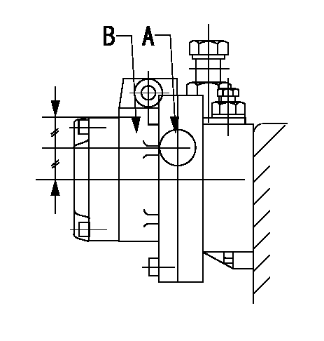
A:Sealing position
B:Pre-stroke actuator
1. When installing the pre-stroke actuator on the pump, first tighten the installation bolts loosely, then move the actuator fully counterclockwise (viewed from the drive side).
Temporary tightening torque: 1 - 1.5 N.m (0.1 - 0.15 kgf.m)
2. Move the actuator in the clockwise direction when viewed from the drive side, and adjust so that it becomes the adjustment point of the adjustment value. Then tighten it.
Tightening torque: 7^9 N.m (0.7^0.9 kgf.m)
3. After prestroke actuator installation adjustment, simultaneously stamp both the actuator side and housing side.
----------
----------
----------
----------
0000002201 RACK SENSOR

(VR) measurement voltage
(I) Part number of the control unit
(G) Apply red paint.
(H): End surface of the pump
1. Rack limit adjustment
(1)Mount the joint (B).
(2)Select the shim (D) so that the rack limit's rack position is obtained at that time.
(3)Install the rod (E) to the block (C).
The distance between the pump end face and the rod (E) at rack limit must be L.
2. Rack sensor adjustment (-0020)
(1)Screw in the bobbin (A) until it contacts the joint (B).
(2)Fix the speed control lever at the full side.
(3)Set at speed N.
(4)Adjust the depth that the bobbin (A) is screwed in so that the control unit's rack sensor output voltage is VR+-0.01 (V), then tighten the nut (F). (If equipped with a boost compensator, perform with boost pressure applied.)
(5)Adjust the bobbin (A) so that the rack sensor's output voltage is VR+-0.01.
(6)Apply G at two places.
Connecting part between the joint (B) and the nut (F)
Connecting part between the joint (B) and the end surface of the pump (H)
----------
L=38-0.2mm N=900r/min Ra=(10.7)mm
----------
----------
L=38-0.2mm N=900r/min Ra=(10.7)mm
----------
0000002301 GOVERNOR TORQUE CONTROL

Dr:Torque control stroke
(A): Without torque control spring capsule
1. Adjustment procedures
(1)Procedure is the same as that for the RFD (former type), except that the positive torque control stroke must be determined at the full lever setting.
2. Procedures for adjustment
(1)Remove the torque control spring capsule.
(2)Operate the pump at approximately N1. (End of idling spring operation < N1.)
(3)Tilt the lever to the full side.
(4)Set so that R = RF.
(5)Increase the speed by pushing in the screw (attached to the bracket on the rear of the tension lever) through the adjusting window.
(6)Adjust so that the torque control stroke Dr1 can be obtained.
(7)Align N2 and N3 with the torque control spring capsule.
3. Final confirmation
(1)After final confirmation, temporarily set the load lever to N = N1, R = idling position.
(2)From this condition, increase speed to N = N4.
(3)Confirm that positive torque control stroke is Dr2.
----------
N1=500r/min N2=(580)r/min N3=(655)r/min N4=1100r/min RF=10.1mm Dr1=0.6mm Dr2=0+0.3mm
----------
----------
N1=500r/min N2=(580)r/min N3=(655)r/min N4=1100r/min RF=10.1mm Dr1=0.6mm Dr2=0+0.3mm
----------
Information:
Product smu/age whichever comes first Caterpillar Dealer Suggested Customer Suggested
Parts % Labor Hrs% Parts % Labor Hrs% Parts % Labor Hrs%
*******Group 2*******
0-6000 hrs,
0-48 mo 100.0% 100.0% 0.0% 0.0% 0.0% 0.0%
This is a 4.0-hour job for Group 2
PARTS DISPOSITION
Handle the parts in accordance with your Warranty Bulletin on warranty parts handling.
Rework Procedure
1. Park the machine on level ground, lower all implements to the ground, shut off machine, and relieve all hydraulic system pressure.
2. Read and understand this Rework Procedure before starting work.
3. See Image 1.2.1 for the general location of the DEF Module Group and reference views that will be used in future steps.
Image1.2.1
(A) Fuel tank; (B) Diesel Exhaust Fluid (DEF) Module Group
DEF tank cover not shown for clarity
4. Inspect control harness assembly (2) at location (AA) and hose assembly (3) at location (BB) for rubbing and or fouling on the DEF Tank Cover (See Image 1.4.1). If either item is damaged, replace both assembly (2) and (3).
396-3862 Control Harness Assembly (2) is compatible with serial numbers equipped WITHOUT a DEF Quality Sensor (FMC1-00772). 524-5527 Control Harness Assembly (2) is compatible with serial numbers equipped WITH a DEF Quality Sensor (FMC00773-Up).
Hardware (C) holding the DEF Module Group to the fuel tank and clamp (E) holding DEF Fill Hose (D) to the tank will need to be loosened to reposition the DEF Module Group to access control harness assembly (2) and hose assembly (3).
Image1.4.1
5. After control harness assembly (2) and hose assembly (3) have been inspected and found without damage OR replaced, secure both parts using Steps 6 through 9.
6. Secure control harness assembly (2) and hose assembly (3) to left side of DEF Module (F) using tie straps (4). (See Image 1.6.1)
The Fuel tank is not shown for clarity.
Image1.6.1
At location (CC), use tie straps (4) to secure harness bundles (G) to prevent harness from contacting the fuel tank. (See Image 1.7.1)
Image1.7.1
At location (DD), use tie straps (4) to secure control harness assembly (2) and hose assembly (3), and terminating resistor (H) at lower location. (See Image 1.8.1)
Image1.8.1
7. Reposition the DEF Module Group, install 560-4252 Bracket Assembly (1), and reinstall the remaining hardware (C), clamp (E) removed in Step 4. Check to make sure control harness assembly (2) and hose assembly (3) will not contact the DEF Tank Cover. (See Image 1.9.1)
Image1.9.1
8. Secure control harness assembly (2) and hose assembly (3) to top of DEF Module Group using tie straps (4) as shown in Image 1.10.1. Check to make sure control harness assembly (2) and hose assembly (3) will not contact the DEF Tank Cover.
Note: Existing P-clip (J) will need to be flipped from the original position.
Image1.10.1
9. Secure control harness assembly (2) and hose assembly (3) to the rear and right side of Diesel Exhaust Fluid Module using tie straps (4) as shown in Image 1.11.1. Check to make sure control harness assembly (2) and hose assembly (3) will not contact the DEF Tank Cover.
Image1.11.1