Information injection-pump assembly
ZEXEL
108822-2720
1088222720
Rating:
Cross reference number
ZEXEL
108822-2720
1088222720
Zexel num
Bosch num
Firm num
Name
108822-2720
INJECTION-PUMP ASSEMBLY
Calibration Data:
Adjustment conditions
Test oil
1404 Test oil ISO4113 or {SAEJ967d}
1404 Test oil ISO4113 or {SAEJ967d}
Test oil temperature
degC
40
40
45
Nozzle and nozzle holder
105780-8250
Bosch type code
1 688 901 101
Nozzle
105780-0120
Bosch type code
1 688 901 990
Nozzle holder
105780-2190
Opening pressure
MPa
20.7
Opening pressure
kgf/cm2
211
Injection pipe
Outer diameter - inner diameter - length (mm) mm 8-3-600
Outer diameter - inner diameter - length (mm) mm 8-3-600
Overflow valve
131425-0220
Overflow valve opening pressure
kPa
157
123
191
Overflow valve opening pressure
kgf/cm2
1.6
1.25
1.95
Tester oil delivery pressure
kPa
255
255
255
Tester oil delivery pressure
kgf/cm2
2.6
2.6
2.6
PS/ACT control unit part no.
407980-2
24*
Digi switch no.
42
Direction of rotation (viewed from drive side)
Right R
Right R
Injection timing adjustment
Direction of rotation (viewed from drive side)
Right R
Right R
Injection order
1-2-7-3-
4-5-6-8
Pre-stroke
mm
8.5
8.47
8.53
Beginning of injection position
Governor side NO.1
Governor side NO.1
Difference between angles 1
Cyl.1-2 deg. 45 44.75 45.25
Cyl.1-2 deg. 45 44.75 45.25
Difference between angles 2
Cal 1-7 deg. 90 89.75 90.25
Cal 1-7 deg. 90 89.75 90.25
Difference between angles 3
Cal 1-3 deg. 135 134.75 135.25
Cal 1-3 deg. 135 134.75 135.25
Difference between angles 4
Cal 1-4 deg. 180 179.75 180.25
Cal 1-4 deg. 180 179.75 180.25
Difference between angles 5
Cal 1-5 deg. 225 224.75 225.25
Cal 1-5 deg. 225 224.75 225.25
Difference between angles 6
Cal 1-6 deg. 270 269.75 270.25
Cal 1-6 deg. 270 269.75 270.25
Difference between angles 7
Cal 1-8 deg. 315 314.75 315.25
Cal 1-8 deg. 315 314.75 315.25
Injection quantity adjustment
Adjusting point
-
Rack position
13.3
Pump speed
r/min
650
650
650
Average injection quantity
mm3/st.
136.5
134.9
138.1
Max. variation between cylinders
%
0
-3
3
Basic
*
Fixing the rack
*
PS407980-224*
V
2.45+-0.
01
PS407980-224*
mm
6.1+-0.0
5
Standard for adjustment of the maximum variation between cylinders
*
Injection quantity adjustment_02
Adjusting point
Z
Rack position
8.7+-0.5
Pump speed
r/min
345
345
345
Average injection quantity
mm3/st.
23.5
20.9
26.1
Max. variation between cylinders
%
0
-15
15
Fixing the rack
*
PS407980-224*
V
V1+0.05+
-0.01
PS407980-224*
mm
8.4+-0.0
3
Standard for adjustment of the maximum variation between cylinders
*
Remarks
Refer to items regarding the pre-stroke actuator
Refer to items regarding the pre-stroke actuator
Injection quantity adjustment_03
Adjusting point
A
Rack position
R1(13.3)
Pump speed
r/min
650
650
650
Average injection quantity
mm3/st.
136.5
135.5
137.5
Basic
*
Fixing the lever
*
PS407980-224*
V
2.45+-0.
01
PS407980-224*
mm
6.1+-0.0
5
Injection quantity adjustment_04
Adjusting point
B
Rack position
R1+1.5
Pump speed
r/min
1100
1100
1100
Average injection quantity
mm3/st.
137
133
141
Fixing the lever
*
PS407980-224*
V
2.45+-0.
01
PS407980-224*
mm
6.1+-0.0
5
Injection quantity adjustment_05
Adjusting point
C
Rack position
(R1-0.7)
Pump speed
r/min
500
500
500
Average injection quantity
mm3/st.
132.5
128.5
136.5
Fixing the lever
*
PS407980-224*
V
2.45+-0.
01
PS407980-224*
mm
6.1+-0.0
5
0000001601
Pre-stroke
mm
8.5
8.47
8.53
Remarks
When the timing sleeve is pushed up
When the timing sleeve is pushed up
_02
Connector angle
deg.
8.5
8
9
Remarks
When the eccentric pin is tightened
When the eccentric pin is tightened
_03
Supply voltage
V
24
23.5
24.5
Ambient temperature
degC
23
18
28
Pre-stroke
mm
6.1
6.05
6.15
Output voltage
V
2.45
2.44
2.46
Adjustment
*
_04
Supply voltage
V
24
23.5
24.5
Ambient temperature
degC
23
18
28
Pre-stroke
mm
8.5
8.47
8.53
Output voltage
V
1.2
1
1.4
Confirmation
*
Remarks
Output voltage V1
Output voltage V1
_05
Supply voltage
V
24
23.5
24.5
Ambient temperature
degC
23
18
28
Pre-stroke
mm
5.5
Output voltage
V
3
2.98
3
Confirmation
*
_06
Supply voltage
V
24
23.5
24.5
Ambient temperature
degC
23
18
28
Output voltage
V
3.05
3.05
Confirmation of operating range
*
Test data Ex:
Governor adjustment
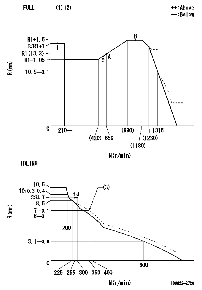
N:Pump speed
R:Rack position (mm)
(1)Torque cam stamping: T1
(2)Tolerance for racks not indicated: +-0.05mm.
(3)Damper spring setting
----------
T1=AC49
----------
----------
T1=AC49
----------
Speed control lever angle
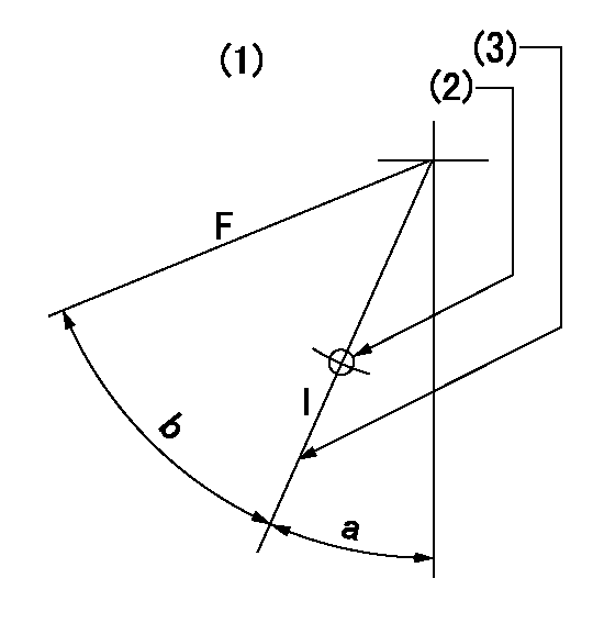
F:Full speed
I:Idle
(1)Viewed from feed pump side.
(2)Use the hole at R = aa
(3)Stopper bolt set position 'H'
----------
aa=37.5mm
----------
a=34deg+-5deg b=(42deg)+-3deg
----------
aa=37.5mm
----------
a=34deg+-5deg b=(42deg)+-3deg
Stop lever angle
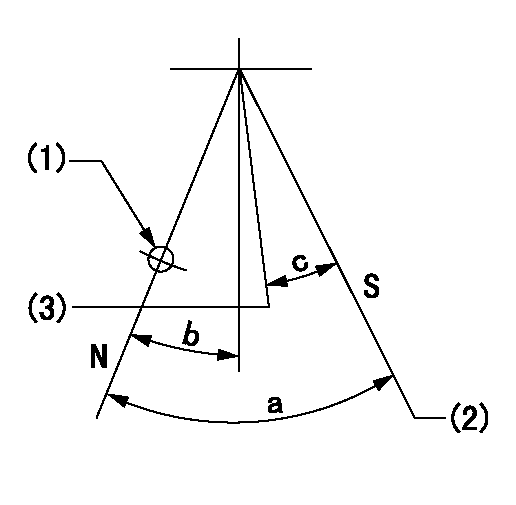
N:Pump normal
S:Stop the pump.
(1)Use the hole at R = aa
(2)Set the stopper bolt so that speed = bb and rack position = cc. (Confirm non-injection.)
(3)Normal engine position (Rack position corresponding to dd)
----------
aa=54mm bb=1100r/min cc=3.5+-0.3mm dd=18mm
----------
a=41deg+-5deg b=5.5deg+-5deg c=(31deg)
----------
aa=54mm bb=1100r/min cc=3.5+-0.3mm dd=18mm
----------
a=41deg+-5deg b=5.5deg+-5deg c=(31deg)
0000001301

(1)Pump vertical direction
(2)Coupling's key groove position at No 1 cylinder's beginning of injection
(3)At the No 1 cylinder's beginning of injection position, stamp an aligning mark on the damper to align with the pointer's groove.
(4)Damper
(5)Pointer
(6)B.T.D.C.: aa
(7)Pre-stroke: bb
----------
aa=4deg bb=8.5+-0.03mm
----------
a=(45deg) b=(44deg)
----------
aa=4deg bb=8.5+-0.03mm
----------
a=(45deg) b=(44deg)
0000001901

A:Sealing position
B:Pre-stroke actuator
1. When installing the pre-stroke actuator on the pump, first tighten the installation bolts loosely, then move the actuator fully counterclockwise (viewed from the drive side).
Temporary tightening torque: 1 - 1.5 N.m (0.1 - 0.15 kgf.m)
2. Move the actuator in the clockwise direction when viewed from the drive side, and adjust so that it becomes the adjustment point of the adjustment value. Then tighten it.
Tightening torque: 7^9 N.m (0.7^0.9 kgf.m)
3. After prestroke actuator installation adjustment, simultaneously stamp both the actuator side and housing side.
----------
----------
----------
----------
0000002201 MICRO SWITCH
Adjustment of the micro-switch
Adjust the bolt to obtain the following lever position when the micro-switch is ON.
(1)Speed N1
(2)Rack position Ra
----------
N1=335r/min Ra=8.3+-0.1mm
----------
----------
N1=335r/min Ra=8.3+-0.1mm
----------
0000002301 RACK SENSOR

(VR) measurement voltage
(I) Part number of the control unit
(G) Apply red paint.
(H): End surface of the pump
1. Rack sensor adjustment (-0620)
(1)Fix the speed control lever at the full position
(2)Set the speed to N1 r/min.
(If the boost compensator is provided, apply boost pressure.)
(3)Adjust the bobbin (A) so that the rack sensor's output voltage is VR+-0.01.
(4)At that time, rack position must be Ra.
(5)Apply G at two places.
Connecting part between the joint (B) and the nut (F)
Connecting part between the joint (B) and the end surface of the pump (H)
----------
N1=1100r/min Ra=R1(13.3)+1.5mm
----------
----------
N1=1100r/min Ra=R1(13.3)+1.5mm
----------
Information:
PROBLEM
The existing diesel exhaust fluid manifold can fail on certain 2570D, 2670D, 563D, and 573D Wheel Feller Bunchers, and 525D, 535D, 545D, and 555D Wheel Skidders. If the existing DEF manifold fails it can lead to inducements and eventual engine shutdown.
AFFECTED PRODUCT
Model Identification Number
2570D D2500112-00114
2670D D2600208-00211
525D GKP00477-00524, 527
535D MTP00386-00448, 450-453
545D KGP00254-00284, 287
555D PGY00153-00159
563D D6300115-00146
573D D7300209-00226
PARTS NEEDED
Qty
Part Number Description
1 3915262 GASKET
1 5280527 MANIFOLD GP
1 DCUSOFTWARE DCU SOFTWARE
1 ENGSOFTWARE ENGINE SOFTWARE
In order to allow equitable parts availability to all participating dealers, please limit your initial parts order to not exceed 29% of dealership population. This is an initial order recommendation only, and the ultimate responsibility for ordering the total number of parts needed to satisfy the program lies with the dealer.
ACTION REQUIRED
Update the Engine and DCU software files to the latest available in SIS Web. Replace the existing diesel exhaust fluid manifold with the 528-0527 diesel exhaust fluid manifold. Use a new 391-5262 gasket when installing a new manifold.
SERVICE CLAIM ALLOWANCES
Product smu/age whichever comes first Caterpillar Dealer Suggested Customer Suggested
Parts % Labor Hrs% Parts % Labor Hrs% Parts % Labor Hrs%
0-6000 hrs,
0-36 mo 100.0% 100.0% 0.0% 0.0% 0.0% 0.0%
6001-8000 hrs,
37-48 mo 33.0% 50.0% 0.0% 0.0% 50.0% 50.0%
This is a 2.0-hour job
PARTS DISPOSITION
Handle the parts in accordance with your Warranty Bulletin on warranty parts handling.
Have questions with 108822-2720?
Group cross 108822-2720 ZEXEL
Mitsubishi
Mitsubishi
108822-2720
INJECTION-PUMP ASSEMBLY