Information injection-pump assembly
ZEXEL
108822-2550
1088222550

Rating:
Compare Prices: .
As an associate, we earn commssions on qualifying purchases through the links below

Fuel Injection Pump ME094766 108822-2550 Suitable for Mitsubishi 8DC11 Engine
Yuubryczny Part Name: Fuel Injection Pump || Part Number:ME094766 108822-2550 || Application:Suitable for Mitsubishi 8DC11 Engine || Notice:Application information provided is for reference only. Please confirm the part number and compare old parts before purchase. If you have any question,pls feel free to ask us. || Friendly tips:This product boasts excellent performance, superior quality, reliability and safety. It is your reliable choice.
Yuubryczny Part Name: Fuel Injection Pump || Part Number:ME094766 108822-2550 || Application:Suitable for Mitsubishi 8DC11 Engine || Notice:Application information provided is for reference only. Please confirm the part number and compare old parts before purchase. If you have any question,pls feel free to ask us. || Friendly tips:This product boasts excellent performance, superior quality, reliability and safety. It is your reliable choice.
Fuel Injection Pump ME094766 108822-2550 Suitable for Mitsubishi 8DC11 Engine
TuneCrumph 🚕Part Name: Fuel Injection Pump || 🚕Part Number:ME094766 108822-2550 || 🚕Application:Suitable for Mitsubishi 8DC11 Engine || 🚕Attention: Dear buyers, precise matching of auto parts is the prerequisite for safe installation! To avoid the problems such as returns, exchanges or installation hazards caused by incorrect model selection, please carefully read and verify the model before placing your order. Thank you for your support! || 🚕NOTE:We are fully aware that your satisfaction is the driving force for the growth of our brand. Thank you for giving us the opportunity to serve you. If there is anything we haven't covered, please give us your feedback directly. Your suggestions are extremely precious to us!
TuneCrumph 🚕Part Name: Fuel Injection Pump || 🚕Part Number:ME094766 108822-2550 || 🚕Application:Suitable for Mitsubishi 8DC11 Engine || 🚕Attention: Dear buyers, precise matching of auto parts is the prerequisite for safe installation! To avoid the problems such as returns, exchanges or installation hazards caused by incorrect model selection, please carefully read and verify the model before placing your order. Thank you for your support! || 🚕NOTE:We are fully aware that your satisfaction is the driving force for the growth of our brand. Thank you for giving us the opportunity to serve you. If there is anything we haven't covered, please give us your feedback directly. Your suggestions are extremely precious to us!

Fuel Injection Pump ME094766 108822-2550 Suitable for Mitsubishi 8DC11 Engine
OfkZynodor Part Name: Fuel Injection Pump || Part Number:ME094766 108822-2550 || Application:Suitable for Mitsubishi 8DC11 Engine || Please make sure to carefully compare the photos and check the part numbers before making the purchase. If you are unable to confirm your engine model or part number, please leave us a message and we will assist you in confirming that the product you purchase is the one you need. || Your order is not merely a single purchase but the beginning of a cooperative journey, aiming to ensure the safe and smooth operation of your vehicle. We are proud to offer you reliable precision engineering components and unparalleled services.
OfkZynodor Part Name: Fuel Injection Pump || Part Number:ME094766 108822-2550 || Application:Suitable for Mitsubishi 8DC11 Engine || Please make sure to carefully compare the photos and check the part numbers before making the purchase. If you are unable to confirm your engine model or part number, please leave us a message and we will assist you in confirming that the product you purchase is the one you need. || Your order is not merely a single purchase but the beginning of a cooperative journey, aiming to ensure the safe and smooth operation of your vehicle. We are proud to offer you reliable precision engineering components and unparalleled services.
Cross reference number
ZEXEL
108822-2550
1088222550
Zexel num
Bosch num
Firm num
Name
108822-2550
INJECTION-PUMP ASSEMBLY
14CK TICS HD-TI8M TICS
14CK TICS HD-TI8M TICS
Calibration Data:
Adjustment conditions
Test oil
1404 Test oil ISO4113 or {SAEJ967d}
1404 Test oil ISO4113 or {SAEJ967d}
Test oil temperature
degC
40
40
45
Nozzle and nozzle holder
105780-8250
Bosch type code
1 688 901 101
Nozzle
105780-0120
Bosch type code
1 688 901 990
Nozzle holder
105780-2190
Opening pressure
MPa
20.7
Opening pressure
kgf/cm2
211
Injection pipe
Outer diameter - inner diameter - length (mm) mm 8-3-600
Outer diameter - inner diameter - length (mm) mm 8-3-600
Overflow valve
131425-0220
Overflow valve opening pressure
kPa
157
157
157
Overflow valve opening pressure
kgf/cm2
1.6
1.6
1.6
Tester oil delivery pressure
kPa
255
255
255
Tester oil delivery pressure
kgf/cm2
2.6
2.6
2.6
PS/ACT control unit part no.
407980-2
24*
Digi switch no.
42
Direction of rotation (viewed from drive side)
Right R
Right R
Injection timing adjustment
Direction of rotation (viewed from drive side)
Right R
Right R
Injection order
1-2-7-3-
4-5-6-8
Pre-stroke
mm
8.5
8.47
8.53
Beginning of injection position
Governor side NO.1
Governor side NO.1
Difference between angles 1
Cyl.1-2 deg. 45 44.75 45.25
Cyl.1-2 deg. 45 44.75 45.25
Difference between angles 2
Cal 1-7 deg. 90 89.75 90.25
Cal 1-7 deg. 90 89.75 90.25
Difference between angles 3
Cal 1-3 deg. 135 134.75 135.25
Cal 1-3 deg. 135 134.75 135.25
Difference between angles 4
Cal 1-4 deg. 180 179.75 180.25
Cal 1-4 deg. 180 179.75 180.25
Difference between angles 5
Cal 1-5 deg. 225 224.75 225.25
Cal 1-5 deg. 225 224.75 225.25
Difference between angles 6
Cal 1-6 deg. 270 269.75 270.25
Cal 1-6 deg. 270 269.75 270.25
Difference between angles 7
Cal 1-8 deg. 315 314.75 315.25
Cal 1-8 deg. 315 314.75 315.25
Injection quantity adjustment
Adjusting point
-
Rack position
13.3
Pump speed
r/min
650
650
650
Average injection quantity
mm3/st.
136.5
134.9
138.1
Max. variation between cylinders
%
0
-3
3
Basic
*
Fixing the rack
*
PS407980-224*
V
2.45+-0.
01
PS407980-224*
mm
6.1+-0.0
5
Standard for adjustment of the maximum variation between cylinders
*
Injection quantity adjustment_02
Adjusting point
Z
Rack position
8.7+-0.5
Pump speed
r/min
345
345
345
Average injection quantity
mm3/st.
23.5
20.9
26.1
Max. variation between cylinders
%
0
-15
15
Fixing the rack
*
PS407980-224*
V
V1+0.05+
-0.01
PS407980-224*
mm
8.4+-0.0
3
Standard for adjustment of the maximum variation between cylinders
*
Remarks
Refer to items regarding the pre-stroke actuator
Refer to items regarding the pre-stroke actuator
Injection quantity adjustment_03
Adjusting point
A
Rack position
R1(13.3)
Pump speed
r/min
650
650
650
Average injection quantity
mm3/st.
136.5
135.5
137.5
Basic
*
Fixing the lever
*
PS407980-224*
V
2.45+-0.
01
PS407980-224*
mm
6.1+-0.0
5
Injection quantity adjustment_04
Adjusting point
B
Rack position
R1+1.35
Pump speed
r/min
1100
1100
1100
Average injection quantity
mm3/st.
136.5
132.5
140.5
Fixing the lever
*
PS407980-224*
V
2.45+-0.
01
PS407980-224*
mm
6.1+-0.0
5
Injection quantity adjustment_05
Adjusting point
C
Rack position
(R1-0.7)
Pump speed
r/min
500
500
500
Average injection quantity
mm3/st.
132.5
128.5
136.5
Fixing the lever
*
PS407980-224*
V
2.45+-0.
01
PS407980-224*
mm
6.1+-0.0
5
0000001601
Pre-stroke
mm
8.5
8.47
8.53
Remarks
When the timing sleeve is pushed up
When the timing sleeve is pushed up
_02
Connector angle
deg.
8.5
8
9
Remarks
When the eccentric pin is tightened
When the eccentric pin is tightened
_03
Supply voltage
V
24
23.5
24.5
Ambient temperature
degC
23
22.5
23.5
Pre-stroke
mm
6.1
6.05
6.15
Output voltage
V
2.45
2.44
2.46
Adjustment
*
_04
Supply voltage
V
24
23.5
24.5
Ambient temperature
degC
23
22.5
23.5
Pre-stroke
mm
8.5
8.47
8.53
Output voltage
V
1.2
1
1.4
Confirmation
*
Remarks
Output voltage V1
Output voltage V1
_05
Supply voltage
V
24
23.5
24.5
Ambient temperature
degC
23
22.5
23.5
Pre-stroke
mm
5.5
Output voltage
V
3
2.98
3
Confirmation
*
_06
Supply voltage
V
24
23.5
24.5
Ambient temperature
degC
23
22.5
23.5
Output voltage
V
3.05
3.05
Confirmation of operating range
*
Test data Ex:
Governor adjustment
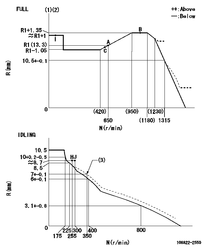
N:Pump speed
R:Rack position (mm)
(1)Torque cam stamping: T1
(2)Tolerance for racks not indicated: +-0.05mm.
(3)Damper spring setting
----------
T1=AD93
----------
----------
T1=AD93
----------
Speed control lever angle
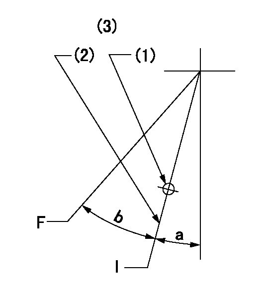
F:Full speed
I:Idle
(1)Use the hole at R = aa
(2)Stopper bolt setting
(3)Viewed from feed pump side.
----------
aa=37.5mm
----------
a=34deg+-5deg b=(42deg)+-3deg
----------
aa=37.5mm
----------
a=34deg+-5deg b=(42deg)+-3deg
Stop lever angle
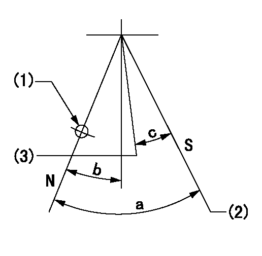
N:Pump normal
S:Stop the pump.
(1)Use the hole at R = aa
(2)Set the stopper bolt so that speed = bb and rack position = cc. (Confirm non-injection.)
(3)Normal engine position (equivalent to R = dd).
----------
aa=54mm bb=1100r/min cc=3.5+-0.3mm dd=18mm
----------
a=41deg+-5deg b=5.5deg+-5deg c=(31deg)
----------
aa=54mm bb=1100r/min cc=3.5+-0.3mm dd=18mm
----------
a=41deg+-5deg b=5.5deg+-5deg c=(31deg)
0000001301

(1)Pump vertical direction
(2)Coupling's key groove position at No 1 cylinder's beginning of injection
(3)At the No 1 cylinder's beginning of injection position, stamp an aligning mark on the damper to align with the pointer's groove.
(4)Damper
(5)Pointer
(6)B.T.D.C.: aa
(7)Pre-stroke: bb
----------
aa=4deg bb=8.5+-0.03mm
----------
a=(45deg) b=(44deg)
----------
aa=4deg bb=8.5+-0.03mm
----------
a=(45deg) b=(44deg)
0000001901

A:Sealing position
B:Pre-stroke actuator
1. When installing the pre-stroke actuator on the pump, first tighten the installation bolts loosely, then move the actuator fully counterclockwise (viewed from the drive side).
Temporary tightening torque: 1 - 1.5 N.m (0.1 - 0.15 kgf.m)
2. Move the actuator in the clockwise direction when viewed from the drive side, and adjust so that it becomes the adjustment point of the adjustment value. Then tighten it.
Tightening torque: 7^9 N.m (0.7^0.9 kgf.m)
3. After prestroke actuator installation adjustment, simultaneously stamp both the actuator side and housing side.
----------
----------
----------
----------
0000002201 RACK SENSOR

(VR) measurement voltage
(I) Part number of the control unit
(G) Apply red paint.
(H): End surface of the pump
1. Rack sensor adjustment (-0620)
(1)Fix the speed control lever at the full position
(2)Set the speed to N1 r/min.
(If the boost compensator is provided, apply boost pressure.)
(3)Adjust the bobbin (A) so that the rack sensor's output voltage is VR+-0.01.
(4)At that time, rack position must be Ra.
(5)Apply G at two places.
Connecting part between the joint (B) and the nut (F)
Connecting part between the joint (B) and the end surface of the pump (H)
----------
N1=1100r/min Ra=R1(13.3)+1.35mm
----------
----------
N1=1100r/min Ra=R1(13.3)+1.35mm
----------
Information:
Start By:a. remove oil pump 1. Check each connecting rod cap for its location on the crankshaft. Each cap must have a number (1) which is the same as the number on the connecting rod. Do not mix bearings.2. Turn the crankshaft until two of the pistons are at bottom center.3. Remove connecting rod caps (2). Remove the lower bearing from the connecting rod caps.4. Push the connecting rods away from the crankshaft and remove the upper bearings from the connecting rods.
Be careful not to damage the crankshaft journals. Do not turn the crankshaft while any of the connecting rod caps are removed.
5. Install the upper bearings in connecting rods. put clean engine oil on the bearings and on the crankshaft journals. Slowly pull the connecting rods on the crankshaft.6. Put clean oil on the lower bearings. Install the lower bearings in the connecting rod caps. Be sure tab (3) on the back of the bearings fits in the groove of the caps and connecting rods. 7. Check the bearing clearance with Plastigage (A) as follows:a. Put clean oil on the threads of bolts (4). Install caps (5), Tool (A) and nuts finger tight.b. Tighten each nut (6) to a torque of 80 8 N m (60 6 lb ft).c. Put a mark across the nuts and bolts. Tighten the nuts 120 degrees more. 8. Remove caps (5) and Plastigage (A). Make sure the connecting rod bearing caps are installed with their identification number in arrangement with the connecting rod number.
Do not use an impact wrench to tighten the nuts the additional 120 degrees.
9. Measure the thickness of the Plastigage to find the bearing clearance. the clearance for new bearings must be 0.071 to 0.168 mm (.0028 to .0066 in). The maximum clearance for used bearings is 0.25 mm (0.010 in).10. Install caps (5). Tighten nuts (6) to a torque of 80 8 N m (60 6 lb ft). Tighten the nuts 120 degrees more.11. Do Steps 1 through 10 for the other connecting rod bearings.End By:a. install oil pump
Have questions with 108822-2550?
Group cross 108822-2550 ZEXEL
Mitsubishi
Mitsubishi
Mitsubishi
Mitsubishi
Mitsubishi
108822-2550
INJECTION-PUMP ASSEMBLY