Information injection-pump assembly
ZEXEL
108822-2150
1088222150
Rating:
Cross reference number
ZEXEL
108822-2150
1088222150
Zexel num
Bosch num
Firm num
Name
108822-2150
INJECTION-PUMP ASSEMBLY
Calibration Data:
Adjustment conditions
Test oil
1404 Test oil ISO4113 or {SAEJ967d}
1404 Test oil ISO4113 or {SAEJ967d}
Test oil temperature
degC
40
40
45
Nozzle and nozzle holder
105780-8250
Bosch type code
1 688 901 101
Nozzle
105780-0120
Bosch type code
1 688 901 990
Nozzle holder
105780-2190
Opening pressure
MPa
20.7
Opening pressure
kgf/cm2
211
Injection pipe
Outer diameter - inner diameter - length (mm) mm 8-3-600
Outer diameter - inner diameter - length (mm) mm 8-3-600
Overflow valve
131425-0220
Overflow valve opening pressure
kPa
157
123
191
Overflow valve opening pressure
kgf/cm2
1.6
1.25
1.95
Tester oil delivery pressure
kPa
255
255
255
Tester oil delivery pressure
kgf/cm2
2.6
2.6
2.6
PS/ACT control unit part no.
407980-2
24*
Digi switch no.
42
Direction of rotation (viewed from drive side)
Right R
Right R
Injection timing adjustment
Direction of rotation (viewed from drive side)
Right R
Right R
Injection order
1-2-7-3-
4-5-6-8
Pre-stroke
mm
8.5
8.47
8.53
Beginning of injection position
Governor side NO.1
Governor side NO.1
Difference between angles 1
Cyl.1-2 deg. 45 44.75 45.25
Cyl.1-2 deg. 45 44.75 45.25
Difference between angles 2
Cal 1-7 deg. 90 89.75 90.25
Cal 1-7 deg. 90 89.75 90.25
Difference between angles 3
Cal 1-3 deg. 135 134.75 135.25
Cal 1-3 deg. 135 134.75 135.25
Difference between angles 4
Cal 1-4 deg. 180 179.75 180.25
Cal 1-4 deg. 180 179.75 180.25
Difference between angles 5
Cal 1-5 deg. 225 224.75 225.25
Cal 1-5 deg. 225 224.75 225.25
Difference between angles 6
Cal 1-6 deg. 270 269.75 270.25
Cal 1-6 deg. 270 269.75 270.25
Difference between angles 7
Cal 1-8 deg. 315 314.75 315.25
Cal 1-8 deg. 315 314.75 315.25
Injection quantity adjustment
Adjusting point
-
Rack position
13.5
Pump speed
r/min
650
650
650
Average injection quantity
mm3/st.
145.5
143.9
147.1
Max. variation between cylinders
%
0
-3
3
Basic
*
Fixing the rack
*
PS407980-224*
V
2.45+-0.
01
PS407980-224*
mm
6.1+-0.0
5
Standard for adjustment of the maximum variation between cylinders
*
Injection quantity adjustment_02
Adjusting point
Z
Rack position
9+-0.5
Pump speed
r/min
290
290
290
Average injection quantity
mm3/st.
23
21
25
Max. variation between cylinders
%
0
-15
15
Fixing the rack
*
PS407980-224*
V
V1+0.05+
-0.01
PS407980-224*
mm
8.4+-0.0
3
Standard for adjustment of the maximum variation between cylinders
*
Remarks
Refer to items regarding the pre-stroke actuator
Refer to items regarding the pre-stroke actuator
Injection quantity adjustment_03
Adjusting point
A
Rack position
R1(13.5)
Pump speed
r/min
650
650
650
Average injection quantity
mm3/st.
145.5
144.5
146.5
Basic
*
Fixing the lever
*
PS407980-224*
V
2.45+-0.
01
PS407980-224*
mm
6.1+-0.0
5
Injection quantity adjustment_04
Adjusting point
B
Rack position
R1+1.7
Pump speed
r/min
1100
1100
1100
Average injection quantity
mm3/st.
146.5
142.5
150.5
Fixing the lever
*
PS407980-224*
V
2.45+-0.
01
PS407980-224*
mm
6.1+-0.0
5
0000001601
Pre-stroke
mm
8.5
8.47
8.53
Remarks
When the timing sleeve is pushed up
When the timing sleeve is pushed up
_02
Connector angle
deg.
8.5
8
9
Remarks
When the eccentric pin is tightened
When the eccentric pin is tightened
_03
Supply voltage
V
24
23.5
24.5
Ambient temperature
degC
23
18
28
Pre-stroke
mm
6.1
6.05
6.15
Output voltage
V
2.45
2.44
2.46
Adjustment
*
_04
Supply voltage
V
24
23.5
24.5
Ambient temperature
degC
23
18
28
Pre-stroke
mm
8.5
8.47
8.53
Output voltage
V
1.2
1
1.4
Confirmation
*
Remarks
Output voltage V1
Output voltage V1
_05
Supply voltage
V
24
23.5
24.5
Ambient temperature
degC
23
18
28
Pre-stroke
mm
5.5
Output voltage
V
3
2.98
3
Confirmation
*
_06
Supply voltage
V
24
23.5
24.5
Ambient temperature
degC
23
18
28
Output voltage
V
3.05
3.05
Confirmation of operating range
*
Test data Ex:
Governor adjustment
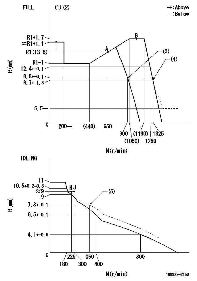
N:Pump speed
R:Rack position (mm)
(1)Torque cam stamping: T1
(2)Tolerance for racks not indicated: +-0.05mm.
(3)Air cylinder OFF
(4)Air cylinder ON
(5)Damper spring setting
----------
T1=AC00
----------
----------
T1=AC00
----------
Speed control lever angle
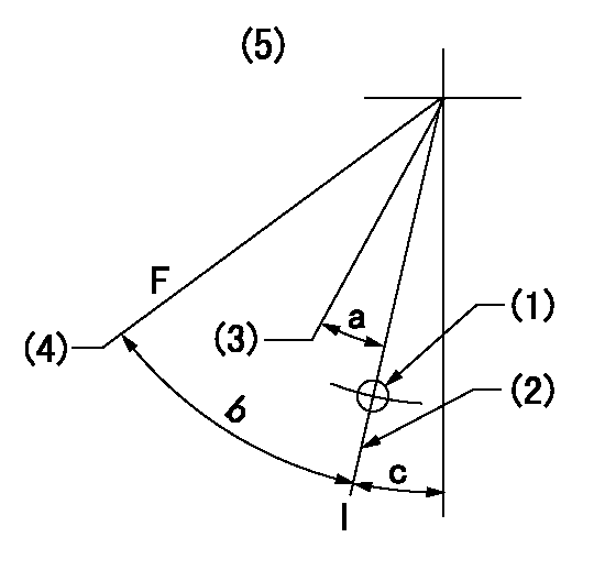
F:Full speed
I:Idle
(1)Use the hole at R = aa
(2)Stopper bolt set position 'H'
(3)When air cylinder OFF.
(4)When air cylinder ON.
(5)Viewed from feed pump side.
----------
aa=37.5mm
----------
a=(17deg) b=30.5deg+-3deg c=30deg+-5deg
----------
aa=37.5mm
----------
a=(17deg) b=30.5deg+-3deg c=30deg+-5deg
Stop lever angle
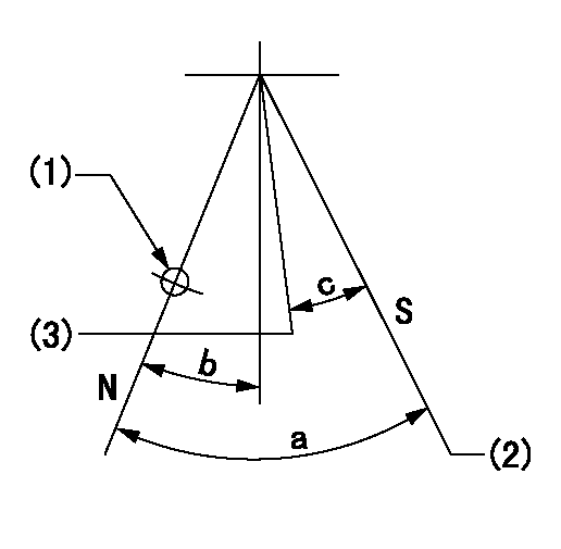
N:Pump normal
S:Stop the pump.
(1)Use the hole at R = aa
(2)Set the stopper bolt so that speed = bb and rack position = cc. (Confirm non-injection.)
(3)Normal engine position (Rack position corresponding to dd)
----------
aa=31.5mm bb=1100r/min cc=4+-0.3mm dd=18mm
----------
a=41deg+-5deg b=13deg+-5deg c=(31deg)
----------
aa=31.5mm bb=1100r/min cc=4+-0.3mm dd=18mm
----------
a=41deg+-5deg b=13deg+-5deg c=(31deg)
0000001301

(1)Pump vertical direction
(2)Coupling's key groove position at No 1 cylinder's beginning of injection
(3)At the No 1 cylinder's beginning of injection position, stamp an aligning mark on the damper to align with the pointer's groove.
(4)Damper
(5)Pointer
(6)B.T.D.C.: aa
(7)Pre-stroke: bb
----------
aa=6deg bb=8.5+-0.03mm
----------
a=45deg16min+-3deg b=(44deg)
----------
aa=6deg bb=8.5+-0.03mm
----------
a=45deg16min+-3deg b=(44deg)
0000001901

A:Sealing position
B:Pre-stroke actuator
1. When installing the pre-stroke actuator on the pump, first tighten the installation bolts loosely, then move the actuator fully counterclockwise (viewed from the drive side).
Temporary tightening torque: 1 - 1.5 N.m (0.1 - 0.15 kgf.m)
2. Move the actuator in the clockwise direction when viewed from the drive side, and adjust so that it becomes the adjustment point of the adjustment value. Then tighten it.
Tightening torque: 7^9 N.m (0.7^0.9 kgf.m)
3. After prestroke actuator installation adjustment, simultaneously stamp both the actuator side and housing side.
----------
----------
----------
----------
0000002201 RACK SENSOR

(VR) measurement voltage
(I) Part number of the control unit
(G) Apply red paint.
(H): End surface of the pump
1. Rack sensor adjustment (-0620)
(1)Fix the speed control lever at the full position
(2)Set the speed to N1 r/min.
(If the boost compensator is provided, apply boost pressure.)
(3)Adjust the bobbin (A) so that the rack sensor's output voltage is VR+-0.01.
(4)At that time, rack position must be Ra.
(5)Apply G at two places.
Connecting part between the joint (B) and the nut (F)
Connecting part between the joint (B) and the end surface of the pump (H)
----------
N1=1100r/min Ra=R1(13.5)+1.7mm
----------
----------
N1=1100r/min Ra=R1(13.5)+1.7mm
----------
0000002301 MICRO SWITCH
Adjustment of the micro-switch
Adjust the bolt to obtain the following lever position when the micro-switch is ON.
(1)Speed N1
(2)Rack position Ra
----------
N1=325r/min Ra=9+-0.1mm
----------
----------
N1=325r/min Ra=9+-0.1mm
----------
0000002401 AIR CYLINDER
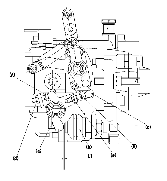
(A) stopper bolt
(B) stopper bolt
(C) stopper bolt
(a) lever
(b) air cylinder
(c) speed lever
(d) Nut
(e) nut
1. Stopper bolt A adjusting method
(1)When air cylinder pressure is P1, set the gap between the lever (a) and the air cylinder (b) to L1.
(2)Apply P2 to the air cylinder.
(3)Confirm that the speed lever (c) operates between idling and full speed positions.
(4)Fix the stopper bolt A using nut d.
2. Stopper bolt <B> adjustment method.
(1)At air cylinder pressure P1, pump speed N1 and rack position is Ra, adjust stopper bolt (B) so that the speed lever (c) is in the stop position.
(2)Move the lever a several times and then fix the stopper bolt B using the nut e.
(3)Nut d tightening torque: T1
(4)Nut e tightening torque: T2
----------
L1=(1)mm P1=0kPa(0kgf/cm2) P2=392+98kPa(4+1kgf/cm2) N1=900r/min Ra=8.8+-0.1mm T1=4.9~7N-m(0.5~0.7kgf-m) T2=4.9~7N-m(0.5~0.7kgf-m)
----------
----------
L1=(1)mm P1=0kPa(0kgf/cm2) P2=392+98kPa(4+1kgf/cm2) N1=900r/min Ra=8.8+-0.1mm T1=4.9~7N-m(0.5~0.7kgf-m) T2=4.9~7N-m(0.5~0.7kgf-m)
----------
Information:
Start By:a. remove oil pump1. Check the main bearing caps for identification for their location and direction in the block. The caps must be installed in the same location and direction from which they were removed. 2. Remove number 2 through number 6 bearing caps (1). Remove thrust plates from the number 4 main bearing.
If the crankshaft is turned in the wrong direction, the tab of the bearing will be pushed between the crankshaft and cylinder block. This can cause damage to either the crankshaft or cylinder block or both.
3. Remove the upper halves of the main bearings by putting Tool (A) in oil hole (2) in the crankshaft. Turn the crankshaft in the direction which will push the end of the bearing with a tab out first.4. Remove the lower halves of the bearings from the caps. Install the bearings dry when the clearance checks are made. Put clean engine oil on the bearings for final assembly.5. Install the new bearings in the caps.6. Install the upper halves of the bearings in the cylinder with Tool (A).
Be sure tabs (3) on the back of the bearings fit in the tab slots of the caps and cylinder block. The serviceman must be very careful to use Plastigage, Tool (B) correctly. The following points must be remembered.
Make sure that the backs of the bearings and the bores are clean and dry.Make sure that the bearing locking tabs are properly seated in their slots.The crankshaft must be free of oil where the Plastigage touches it.If the main bearing clearances are checked with the engine upright or on its side, the crankshaft must be supported. Use a jack under an adjacent crankshaft counterweight and hold the crankshaft against the crown of the bearing. If the crankshaft is not supported, the weight of the crankshaft will cause incorrect readings.Put a piece of Plastigage on the crown of the bearing half that is in the cap. Do not allow the Plastigage to extend over the edge of the bearing.Install the bearing cap using the correct torque-turn specifications. Do not use an impact wrench. Be careful not to dislodge the bearing when the cap is installed.Do not turn the crankshaft with the Plastigage installed.Carefully remove the cap but do not remove the Plastigage. Measure the width of the Plastigage while it is in the bearing cap or on the crankshaft journal. Do this by using the correct scale on the package. Record the measurements.Remove the Plastigage before reinstalling the cap.When using Plastigage, the readings can sometimes be unclear. For example, all parts of the Plastigage are not the same width. Measure the major widths to make sure that they are within the specification range. Also, experience has shown that when checking clearances tighter than 0.10 mm (.004 in) the readings may be low by 0.013 to 0.025 mm (.0005 to .0010 in). Out-of-round journals can give faulty readings. Also, journal taper may be indicated when one end of the Plastigage is wider that the
Have questions with 108822-2150?
Group cross 108822-2150 ZEXEL
Mitsubishi
Mitsubishi
Mitsubishi
Mitsubishi
Mitsubishi
108822-2150
INJECTION-PUMP ASSEMBLY