Information injection-pump assembly
ZEXEL
108822-2091
1088222091
Rating:
Cross reference number
ZEXEL
108822-2091
1088222091
Zexel num
Bosch num
Firm num
Name
108822-2091
INJECTION-PUMP ASSEMBLY
Calibration Data:
Adjustment conditions
Test oil
1404 Test oil ISO4113 or {SAEJ967d}
1404 Test oil ISO4113 or {SAEJ967d}
Test oil temperature
degC
40
40
45
Nozzle and nozzle holder
105780-8250
Bosch type code
1 688 901 101
Nozzle
105780-0120
Bosch type code
1 688 901 990
Nozzle holder
105780-2190
Opening pressure
MPa
20.7
Opening pressure
kgf/cm2
211
Injection pipe
Outer diameter - inner diameter - length (mm) mm 8-3-600
Outer diameter - inner diameter - length (mm) mm 8-3-600
Overflow valve
131425-0220
Overflow valve opening pressure
kPa
157
123
191
Overflow valve opening pressure
kgf/cm2
1.6
1.25
1.95
Tester oil delivery pressure
kPa
255
255
255
Tester oil delivery pressure
kgf/cm2
2.6
2.6
2.6
PS/ACT control unit part no.
407980-2
24*
Digi switch no.
42
Direction of rotation (viewed from drive side)
Right R
Right R
Injection timing adjustment
Direction of rotation (viewed from drive side)
Right R
Right R
Injection order
1-2-7-3-
4-5-6-8
Pre-stroke
mm
8.5
8.47
8.53
Beginning of injection position
Governor side NO.1
Governor side NO.1
Difference between angles 1
Cyl.1-2 deg. 45 44.75 45.25
Cyl.1-2 deg. 45 44.75 45.25
Difference between angles 2
Cal 1-7 deg. 90 89.75 90.25
Cal 1-7 deg. 90 89.75 90.25
Difference between angles 3
Cal 1-3 deg. 135 134.75 135.25
Cal 1-3 deg. 135 134.75 135.25
Difference between angles 4
Cal 1-4 deg. 180 179.75 180.25
Cal 1-4 deg. 180 179.75 180.25
Difference between angles 5
Cal 1-5 deg. 225 224.75 225.25
Cal 1-5 deg. 225 224.75 225.25
Difference between angles 6
Cal 1-6 deg. 270 269.75 270.25
Cal 1-6 deg. 270 269.75 270.25
Difference between angles 7
Cal 1-8 deg. 315 314.75 315.25
Cal 1-8 deg. 315 314.75 315.25
Injection quantity adjustment
Adjusting point
-
Rack position
13.9
Pump speed
r/min
650
650
650
Average injection quantity
mm3/st.
150.5
148.9
152.1
Max. variation between cylinders
%
0
-3
3
Basic
*
Fixing the rack
*
PS407980-224*
V
2.45+-0.
01
PS407980-224*
mm
6.1+-0.0
5
Standard for adjustment of the maximum variation between cylinders
*
Injection quantity adjustment_02
Adjusting point
Z
Rack position
9+-0.5
Pump speed
r/min
320
320
320
Average injection quantity
mm3/st.
23
21
25
Max. variation between cylinders
%
0
-15
15
Fixing the rack
*
PS407980-224*
V
V1+0.05+
-0.01
PS407980-224*
mm
8.4+-0.0
3
Standard for adjustment of the maximum variation between cylinders
*
Remarks
Refer to items regarding the pre-stroke actuator
Refer to items regarding the pre-stroke actuator
Injection quantity adjustment_03
Adjusting point
A
Rack position
R1(13.9)
Pump speed
r/min
650
650
650
Average injection quantity
mm3/st.
150.5
149.5
151.5
Basic
*
Fixing the lever
*
PS407980-224*
V
2.45+-0.
01
PS407980-224*
mm
6.1+-0.0
5
Injection quantity adjustment_04
Adjusting point
B
Rack position
R1+1.7
Pump speed
r/min
1100
1100
1100
Average injection quantity
mm3/st.
154
150
158
Fixing the lever
*
PS407980-224*
V
2.45+-0.
01
PS407980-224*
mm
6.1+-0.0
5
0000001601
Pre-stroke
mm
8.5
8.47
8.53
Remarks
When the timing sleeve is pushed up
When the timing sleeve is pushed up
_02
Connector angle
deg.
8.5
8
9
Remarks
When the eccentric pin is tightened
When the eccentric pin is tightened
_03
Supply voltage
V
24
23.5
24.5
Ambient temperature
degC
23
18
28
Pre-stroke
mm
6.1
6.05
6.15
Output voltage
V
2.45
2.44
2.46
Adjustment
*
_04
Supply voltage
V
24
23.5
24.5
Ambient temperature
degC
23
18
28
Pre-stroke
mm
8.5
8.47
8.53
Output voltage
V
1.2
1
1.4
Confirmation
*
Remarks
Output voltage V1
Output voltage V1
_05
Supply voltage
V
24
23.5
24.5
Ambient temperature
degC
23
18
28
Pre-stroke
mm
5.5
Output voltage
V
3
2.98
3
Confirmation
*
_06
Supply voltage
V
24
23.5
24.5
Ambient temperature
degC
23
18
28
Output voltage
V
3.05
3.05
Confirmation of operating range
*
Test data Ex:
Governor adjustment
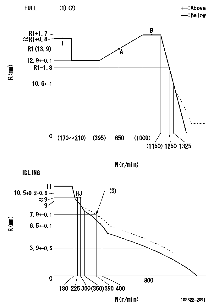
N:Pump speed
R:Rack position (mm)
(1)Torque cam stamping: T1
(2)Tolerance for racks not indicated: +-0.05mm.
(3)Damper spring setting
----------
T1=AC23
----------
----------
T1=AC23
----------
Speed control lever angle
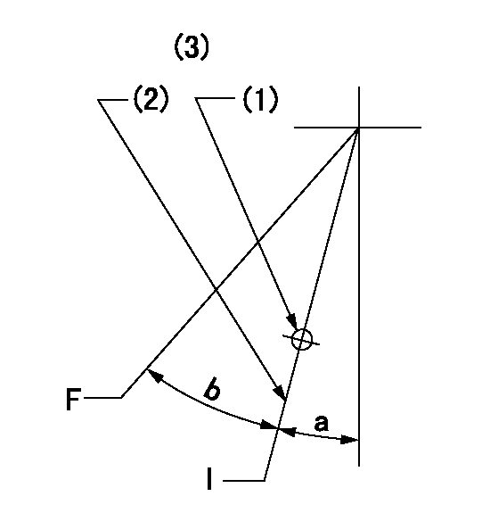
F:Full speed
I:Idle
(1)Use the hole at R = aa
(2)Stopper bolt set position 'H'
(3)Viewed from feed pump side.
----------
aa=37.5mm
----------
a=30deg+-5deg b=(31deg)+-3deg
----------
aa=37.5mm
----------
a=30deg+-5deg b=(31deg)+-3deg
Stop lever angle

N:Pump normal
S:Stop the pump.
(1)Use the hole at R = aa
(2)Set the stopper bolt so that speed = bb and rack position = cc. (Confirm non-injection.)
(3)Normal engine position (equivalent to R = dd).
----------
aa=31.5mm bb=1100r/min cc=4+-0.3mm dd=18mm
----------
a=(31deg) b=13deg+-5deg c=41deg+-5deg
----------
aa=31.5mm bb=1100r/min cc=4+-0.3mm dd=18mm
----------
a=(31deg) b=13deg+-5deg c=41deg+-5deg
0000001301

(1)Pump vertical direction
(2)Coupling's key groove position at No 1 cylinder's beginning of injection
(3)At the No 1 cylinder's beginning of injection position, stamp an aligning mark on the damper to align with the pointer's groove.
(4)Damper
(5)Pointer
(6)B.T.D.C.: aa
(7)Pre-stroke: bb
----------
aa=6deg bb=8.5+-0.03mm
----------
a=(50deg) b=(44deg)
----------
aa=6deg bb=8.5+-0.03mm
----------
a=(50deg) b=(44deg)
0000001901

A:Sealing position
B:Pre-stroke actuator
1. When installing the pre-stroke actuator on the pump, first tighten the installation bolts loosely, then move the actuator fully counterclockwise (viewed from the drive side).
Temporary tightening torque: 1 - 1.5 N.m (0.1 - 0.15 kgf.m)
2. Move the actuator in the clockwise direction when viewed from the drive side, and adjust so that it becomes the adjustment point of the adjustment value. Then tighten it.
Tightening torque: 7^9 N.m (0.7^0.9 kgf.m)
3. After prestroke actuator installation adjustment, simultaneously stamp both the actuator side and housing side.
----------
----------
----------
----------
0000002201 MICRO SWITCH
Adjustment of the micro-switch
Adjust the bolt to obtain the following lever position when the micro-switch is ON.
(1)Speed N1
(2)Rack position Ra
----------
N1=325r/min Ra=9+-0.1mm
----------
----------
N1=325r/min Ra=9+-0.1mm
----------
0000002301 RACK SENSOR

(VR) measurement voltage
(I) Part number of the control unit
(G) Apply red paint.
(H): End surface of the pump
1. Rack sensor adjustment (-0620)
(1)Fix the speed control lever at the full position
(2)Set the speed to N1 r/min.
(If the boost compensator is provided, apply boost pressure.)
(3)Adjust the bobbin (A) so that the rack sensor's output voltage is VR+-0.01.
(4)At that time, rack position must be Ra.
(5)Apply G at two places.
Connecting part between the joint (B) and the nut (F)
Connecting part between the joint (B) and the end surface of the pump (H)
----------
N1=1100r/min Ra=R1(13.9)+1.7mm
----------
----------
N1=1100r/min Ra=R1(13.9)+1.7mm
----------
Information:
Engine Runs Smoothly1. Poor Quality Fuel If poor or low quality fuel is suspected, use a source of known good quality fuel, and prime and start the engine. If the problem is resolved, drain the complete fuel system, replace the fuel filter, and add fuel recommended by Caterpillar.2. Fuel Injection Timing Out Of Calibration Check the fuel injection timing calibration and make necessary calibrations. See Engine Test Procedure Number P-301 in Electronic Troubleshooting, 3176 Vehicular Diesel Engine, Form No. SENR5137.3. Air Inlet Piping Damage Or Restriction Visually inspect the air inlet system for damage or restriction. If leaks are found, repair or replace parts as required.If the air cleaner has an Air Cleaner Service Indicator, check the indicator for the position of the red piston. If the indicator shows red at any time, install a clean or new air cleaner element.Air inlet restriction can be checked with a water manometer or a vacuum gauge [measuring mm (inches) of water]. Make a connection to the piping between the air cleaner and the inlet to the turbocharger. The maximum restriction allowed, with the engine at full load rpm, is 762 mm (30 in) of water. If a water manometer or vacuum gauge is not available, visually check the air filter for dirt. Clean or replace as required.4. Exhaust System Restriction Visually inspect the exhaust system for damage or restriction. If leaks are found, repair or replace parts as required.Exhaust system back pressure (pressure differential between the turbocharger exhaust outlet and atmosphere) should not exceed 686 mm (27 in) of water. An alternative check would be to remove the exhaust piping, load the engine on a chassis dynamometer to determine if the problem is corrected. If this solves the problem, the restriction is in the muffler or vehicle piping.5. Valve Adjustment Not Correct Check and make any necessary adjustments. See the topic, Valve Clearance Setting, in 3176 Vehicular Diesel Engine Systems Operation And Testing and Adjusting, Form No. SENR4964. Intake valve clearance is 0.38 mm (.015 in), and exhaust valve clearance is 0.64 mm (.025 in).6. Defective Unit Injectors A defective unit injector can be found, by running the engine at the rpm where the problem exists, with the use of the Electronic Control Analyzer and Programmer (ECAP) service tool Interactive Diagnostics feature (single cylinder cutout) to stop the fuel supply to each cylinder in turn. If a cylinder is found where the cutout makes a difference in exhaust smoke, that injector should be removed and tested. Drain the fuel supply manifold and remove the injector(s) (see 3176 Vehicular Diesel Engine Disassembly and Assembly, Form No. SENR4965).Testing of the injectors must be done off of the engine. Use the 1U6661 Pop (Injector) Tester Group with a 1U6663 Injector Holding Block, and a 1U6665 Power Supply, to test the injectors. For the test procedure refer to Special Instruction, Form No. SEHS8867, Using The 1U6661 Pop (Injector) Tester. For test specifications refer to Special Instruction, Form No. SEHS8804, Unit Injector Test Specifications
Have questions with 108822-2091?
Group cross 108822-2091 ZEXEL
Mitsubishi
Mitsubishi
Mitsubishi
Mitsubishi
Mitsubishi
Mitsubishi
Mitsubishi
108822-2091
INJECTION-PUMP ASSEMBLY