Information injection-pump assembly
ZEXEL
108822-2050
1088222050
Rating:
Cross reference number
ZEXEL
108822-2050
1088222050
Zexel num
Bosch num
Firm num
Name
108822-2050
INJECTION-PUMP ASSEMBLY
Calibration Data:
Adjustment conditions
Test oil
1404 Test oil ISO4113 or {SAEJ967d}
1404 Test oil ISO4113 or {SAEJ967d}
Test oil temperature
degC
40
40
45
Nozzle and nozzle holder
105780-8230
Nozzle
105780-0110
Nozzle holder
105780-2170
Opening pressure
MPa
17.2
Opening pressure
kgf/cm2
175
Injection pipe
Outer diameter - inner diameter - length (mm) mm 8-3-600
Outer diameter - inner diameter - length (mm) mm 8-3-600
Overflow valve
131425-0220
Overflow valve opening pressure
kPa
157
123
191
Overflow valve opening pressure
kgf/cm2
1.6
1.25
1.95
Tester oil delivery pressure
kPa
255
255
255
Tester oil delivery pressure
kgf/cm2
2.6
2.6
2.6
PS/ACT control unit part no.
407980-2
24*
Digi switch no.
42
Direction of rotation (viewed from drive side)
Right R
Right R
Injection timing adjustment
Direction of rotation (viewed from drive side)
Right R
Right R
Injection order
1-2-7-3-
4-5-6-8
Pre-stroke
mm
8.5
8.47
8.53
Beginning of injection position
Governor side NO.1
Governor side NO.1
Difference between angles 1
Cyl.1-2 deg. 45 44.75 45.25
Cyl.1-2 deg. 45 44.75 45.25
Difference between angles 2
Cal 1-7 deg. 90 89.75 90.25
Cal 1-7 deg. 90 89.75 90.25
Difference between angles 3
Cal 1-3 deg. 135 134.75 135.25
Cal 1-3 deg. 135 134.75 135.25
Difference between angles 4
Cal 1-4 deg. 180 179.75 180.25
Cal 1-4 deg. 180 179.75 180.25
Difference between angles 5
Cal 1-5 deg. 225 224.75 225.25
Cal 1-5 deg. 225 224.75 225.25
Difference between angles 6
Cal 1-6 deg. 270 269.75 270.25
Cal 1-6 deg. 270 269.75 270.25
Difference between angles 7
Cal 1-8 deg. 315 314.75 315.25
Cal 1-8 deg. 315 314.75 315.25
Injection quantity adjustment
Adjusting point
-
Rack position
13.3
Pump speed
r/min
700
700
700
Average injection quantity
mm3/st.
127
125.4
128.6
Max. variation between cylinders
%
0
-3
3
Basic
*
Fixing the rack
*
PS407980-224*
V
2.45+-0.
01
PS407980-224*
mm
6.1+-0.0
5
Standard for adjustment of the maximum variation between cylinders
*
Injection quantity adjustment_02
Adjusting point
Z
Rack position
8.5+-0.5
Pump speed
r/min
290
290
290
Average injection quantity
mm3/st.
23.5
20.9
26.1
Max. variation between cylinders
%
0
-15
15
Fixing the rack
*
PS407980-224*
V
V1+0.05+
-0.01
PS407980-224*
mm
8.4+-0.0
3
Standard for adjustment of the maximum variation between cylinders
*
Remarks
Refer to items regarding the pre-stroke actuator
Refer to items regarding the pre-stroke actuator
Injection quantity adjustment_03
Adjusting point
A
Rack position
R1(13.3)
Pump speed
r/min
700
700
700
Average injection quantity
mm3/st.
127
126
128
Basic
*
Fixing the lever
*
PS407980-224*
V
2.45+-0.
01
PS407980-224*
mm
6.1+-0.0
5
Injection quantity adjustment_04
Adjusting point
B
Rack position
R1+1.55
Pump speed
r/min
1100
1100
1100
Average injection quantity
mm3/st.
129.5
125.5
133.5
Fixing the lever
*
PS407980-224*
V
2.45+-0.
01
PS407980-224*
mm
6.1+-0.0
5
0000001601
Pre-stroke
mm
8.5
8.47
8.53
Remarks
When the timing sleeve is pushed up
When the timing sleeve is pushed up
_02
Connector angle
deg.
8.5
8
9
Remarks
When the eccentric pin is tightened
When the eccentric pin is tightened
_03
Supply voltage
V
24
23.5
24.5
Ambient temperature
degC
23
18
28
Pre-stroke
mm
6.1
6.05
6.15
Output voltage
V
2.45
2.44
2.46
Adjustment
*
_04
Supply voltage
V
24
23.5
24.5
Ambient temperature
degC
23
18
28
Pre-stroke
mm
8.5
8.47
8.53
Output voltage
V
1.2
1
1.4
Confirmation
*
Remarks
Output voltage V1
Output voltage V1
_05
Supply voltage
V
24
23.5
24.5
Ambient temperature
degC
23
18
28
Pre-stroke
mm
5.5
Output voltage
V
3
2.98
3
Confirmation
*
_06
Supply voltage
V
24
23.5
24.5
Ambient temperature
degC
23
18
28
Output voltage
V
3.05
3.05
Confirmation of operating range
*
Test data Ex:
Governor adjustment
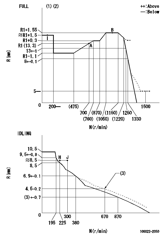
N:Pump speed
R:Rack position (mm)
(1)Torque cam stamping: T1
(2)Tolerance for racks not indicated: +-0.05mm.
(3)Damper spring setting
----------
T1=AB07
----------
----------
T1=AB07
----------
Speed control lever angle
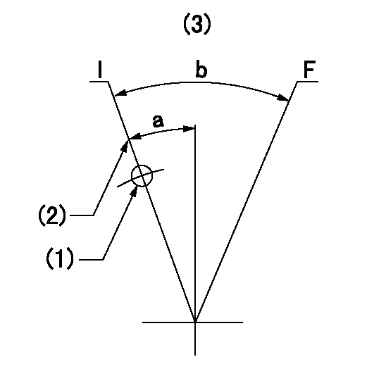
F:Full speed
I:Idle
(1)Use the hole at R = aa
(2)Stopper bolt set position 'H'
(3)Viewed from feed pump side.
----------
aa=30mm
----------
a=37deg+-5deg b=(40deg)+-3deg
----------
aa=30mm
----------
a=37deg+-5deg b=(40deg)+-3deg
Stop lever angle
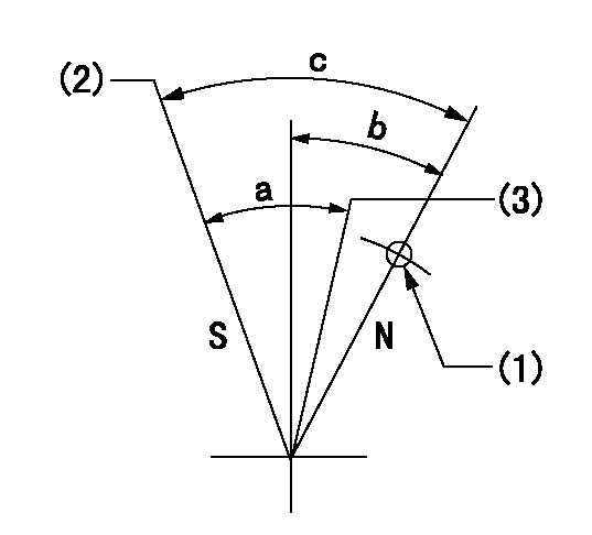
N:Pump normal
S:Stop the pump.
(1)Use the hole at R = aa
(2)Set the stopper bolt so that speed = bb and rack position = cc. (Confirm non-injection.)
(3)Normal engine position (Rack position corresponding to dd)
----------
aa=45mm bb=1100r/min cc=3.5+-0.3mm dd=18mm
----------
a=(31deg)+-5deg b=25.5deg+-5deg c=41deg+-5deg
----------
aa=45mm bb=1100r/min cc=3.5+-0.3mm dd=18mm
----------
a=(31deg)+-5deg b=25.5deg+-5deg c=41deg+-5deg
0000001301

(1)Pump vertical direction
(2)Coupling's key groove position at No 1 cylinder's beginning of injection
(3)At the No 1 cylinder's beginning of injection position, stamp an aligning mark on the damper to align with the pointer's groove.
(4)Damper
(5)Pointer
(6)B.T.D.C.: aa
(7)Pre-stroke: bb
----------
aa=4deg bb=8.5+-0.03mm
----------
a=45deg16min+-3deg b=(44deg)
----------
aa=4deg bb=8.5+-0.03mm
----------
a=45deg16min+-3deg b=(44deg)
0000001901

A:Sealing position
B:Pre-stroke actuator
1. When installing the pre-stroke actuator on the pump, first tighten the installation bolts loosely, then move the actuator fully counterclockwise (viewed from the drive side).
Temporary tightening torque: 1 - 1.5 N.m (0.1 - 0.15 kgf.m)
2. Move the actuator in the clockwise direction when viewed from the drive side, and adjust so that it becomes the adjustment point of the adjustment value. Then tighten it.
Tightening torque: 7^9 N.m (0.7^0.9 kgf.m)
3. After prestroke actuator installation adjustment, simultaneously stamp both the actuator side and housing side.
----------
----------
----------
----------
0000002201 MICRO SWITCH
Adjustment of the micro-switch
Adjust the bolt to obtain the following lever position when the micro-switch is ON.
(1)Speed N1
(2)Rack position Ra
----------
N1=325r/min Ra=8.5+-0.1mm
----------
----------
N1=325r/min Ra=8.5+-0.1mm
----------
0000002301 RACK SENSOR

(VR) measurement voltage
(I) Part number of the control unit
(G) Apply red paint.
(H): End surface of the pump
1. Rack sensor adjustment (-0620)
(1)Fix the speed control lever at the full position
(2)Set the speed to N1 r/min.
(If the boost compensator is provided, apply boost pressure.)
(3)Adjust the bobbin (A) so that the rack sensor's output voltage is VR+-0.01.
(4)At that time, rack position must be Ra.
(5)Apply G at two places.
Connecting part between the joint (B) and the nut (F)
Connecting part between the joint (B) and the end surface of the pump (H)
----------
N1=1100r/min Ra=R1(13.3)+1.55mm
----------
----------
N1=1100r/min Ra=R1(13.3)+1.55mm
----------
Information:
(1) Distance dowels extend past end surface of cylinder block ... 8.0 0.5 mm (.31 .02 in)(2) Bore diameter in cylinder block for the cylinder liners ... 136.00 0.03 mm (5.354 .001 in)(3) Distance dowels extend past end surface of cylinder block ... 8.0 0.5 mm (.31 .02 in) (4) Spacer block.(5) Height of dowels above top surface of spacer block and cylinder block ... 8.00 0.03 mm (.315 .001 in)(6) Cylinder Liner. Make reference to the procedure for checking Cylinder Liner Projection in Testing And Adjusting Section of Service Manual Form No. SENR4964.Cylinder liner projection above the top surface of the spacer block must be ... 0.12 0.08 mm (.005 .003 in)Apply 7M7260 Liquid Gasket as required to cylinder liner shoulder and cylinder block face joint of all liners. (7) Depth plug is to be installed (from end surface of cylinder block to top of plug) ... 1.25 0.25 mm (.049 .010 in)(8) Diameter of camshaft bores ... 75.000 0.025 mm (2.9530 .0010 in)(9) Oil cooling jet assembly. Tighten bolt that holds oil cooling jet to ... 25 7 N m (18 5 1b ft)(10) Width of main bearing cap ... 175.00 0.02 mm (6.8898 .0008 in) Width in cylinder block for main bearing cap ... 175.000 0.018 mm (6.8898 .0007 in)(11) Distance from centerline of crankshaft bore to top surface of cylinder block ... 265.0 mm (10.43 in)The flatness across the top contact surface of the block must be within 0.05 mm (.002 in) for any 150 mm (5.9 in) section of the surface.(12) Distance from centerline of crankshaft to bottom surface of cylinder block ... 120.0 mm (4.72 in)(13) Main bearing cap bolts. Install as follows: Main bearing caps shall be assembled with the part number towards the right side. Caps are to be identified by stamped numbers 1 thru 7 located on the bottom unmachined surface.Main bearing cap bolts are to be lubricated on threads and washer face with SAE 30 oil or molylube. Tighten bolts to 95 5 N m (70 4 lb ft) plus 90 5° additional turn prior to machining. Tighten bolts simultaneously or tighten both bolts to 95 N m (70 lb ft) before turning the additional 90°.(14) Bore in cylinder block for seven main bearings ... 108.000 0.013 mm (4.2520 .0005 in) All main bearing bore measurements are to be made before caps are disassembled.
Have questions with 108822-2050?
Group cross 108822-2050 ZEXEL
Mitsubishi
Mitsubishi
Mitsubishi
108822-2050
INJECTION-PUMP ASSEMBLY