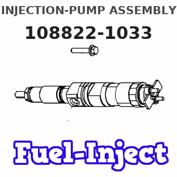
Information injection-pump assembly
BOSCH
9 400 612 736
9400612736
ZEXEL
108822-1033
1088221033
ISUZU
1156033821
1156033821
Rating:
Service parts 108822-1033 INJECTION-PUMP ASSEMBLY:
1.
_
5.
AUTOM. ADVANCE MECHANIS
7.
COUPLING PLATE
11.
Nozzle and Holder
1-15300-345-0
12.
Open Pre:MPa(Kqf/cm2)
17.7{180}/22.1{225}
14.
NOZZLE
Include in #1:
108822-1033
as INJECTION-PUMP ASSEMBLY
Cross reference number
Zexel num
Bosch num
Firm num
Name
Information:
Lubrication System
Oil Lubrication Schematic
Oil Pump
(1) Strainer. (2) Oil Pump relief valve. (3) Oil pump. (4) Idler gear. (5) Crankshaft gear.The lubrication system is the pressure type and the flow of oil goes from the oil pan through strainer (1) into oil pump (3). Oil pump (3) is driven by crankshaft gear (5) through idler gear (4). The oil pump is connected to the front main bearing cap. Relief valve (2) which is spring loaded controls the maximum oil pressure. An oil pressure sending unit is connected to the main oil gallery.Oil under pressure goes from the oil pump through the relief valve and filter. On the T4.236 Engines, oil passes first through the oil cooler. The oil cooler is cooled by water from the cooling system. On engines that have a center mounted balancer unit, the oil pump and relief valve are integral with the balancer unit.Oil flows through the filter to the main oil gallery which is a drilled passage the length of the crankcase. A pipe from the filter head feeds oil to the turbocharger bearings on T4.236 Engines.From the gallery the oil flows through drilled passages to the main bearing bores and then through the crankshaft passages to the big end (rod) bearings. T4.236 Engine oil also flows from the main oil gallery to the piston cooling jets which have integral relief valves. The piston cooling jets feed oil to the underside of the pistons, where the oil circulates, taking heat from the combustion area. The cooling jets start operation at approximately 205 kPa (30 psi).
Timing Gears
(6) Idler gear. (7) Idler gear retainer plate.The crankshaft bearings are lubricated from numbers 1, 3 and 5 main bearings. The camshaft center bearing supplies a controlled amount of oil to the rocker shaft assembly. Oil from the rocker shaft drains through a bleed hole in each rocker lever to lubricate the valves and valve guides.Oil also goes from the gallery through the rear of idler gear (6) hub, then through passages to lubricate the idler gear bearing and gear retainer plate (7).Pistons, cylinder liners, connecting rod small end bushings, cam lobes and tappets (valve lifters) are splash and oil mist lubricated.Balancer Unit
Center Mounted Balancer Unit Components
(1) Idler gear hub. (2) Idler gear bearing. (3) Idler gear. (4) Idler gear thrust washer. (5) Balance weight bushings. (6) Balance weights. (7) Oil transfer cover plate. (8) Balancer frame. (9) Oil pump relief valve assembly. (10) Balance weights drive gear. (11) Gear shaft drive bearings. (12) Gear shaft drive. (13) Oil pump. (14) Oil suction pipe.Engines that are mounted stationary (rigid) have a balancer unit that is mounted to the block bottom face in the center of the engine. The balancer unit is timed to and driven by the crankshaft through a gear on the crankshaft and idler gear (3). The rotation of timed balance weights (10) counteracts the movement of the pistons and connecting rods of the engine.Oil pump (13) is part of and is driven by the balancer unit