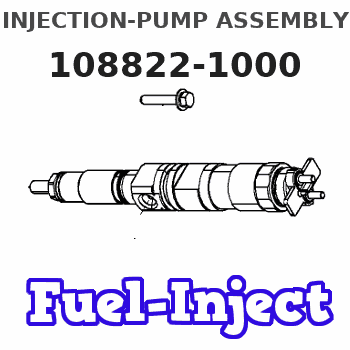
Information injection-pump assembly
BOSCH
9 400 611 486
9400611486
ZEXEL
108822-1000
1088221000
ISUZU
1156031270
1156031270
Rating:
Service parts 108822-1000 INJECTION-PUMP ASSEMBLY:
1.
_
5.
AUTOM. ADVANCE MECHANIS
7.
COUPLING PLATE
9.
_
11.
Nozzle and Holder
1-15300-345-0
12.
Open Pre:MPa(Kqf/cm2)
17.7{180}/22.1{225}
14.
NOZZLE
Include in #1:
108822-1000
as INJECTION-PUMP ASSEMBLY
Cross reference number
BOSCH
9 400 611 486
9400611486
ZEXEL
108822-1000
1088221000
ISUZU
1156031270
1156031270
Zexel num
Bosch num
Firm num
Name
Calibration Data:
Adjustment conditions
Test oil
1404 Test oil ISO4113 or {SAEJ967d}
1404 Test oil ISO4113 or {SAEJ967d}
Test oil temperature
degC
40
40
45
Nozzle and nozzle holder
105780-8250
Bosch type code
1 688 901 101
Nozzle
105780-0120
Bosch type code
1 688 901 990
Nozzle holder
105780-2190
Opening pressure
MPa
20.7
Opening pressure
kgf/cm2
211
Injection pipe
Outer diameter - inner diameter - length (mm) mm 8-3-600
Outer diameter - inner diameter - length (mm) mm 8-3-600
Overflow valve
131424-8120
Overflow valve opening pressure
kPa
255
221
289
Overflow valve opening pressure
kgf/cm2
2.6
2.25
2.95
Tester oil delivery pressure
kPa
255
255
255
Tester oil delivery pressure
kgf/cm2
2.6
2.6
2.6
RED4 control unit part number
407915-0
590
RED4 rack sensor specifications
mm
19
PS/ACT control unit part no.
407980-2
24*
Digi switch no.
41
Direction of rotation (viewed from drive side)
Right R
Right R
Injection timing adjustment
Direction of rotation (viewed from drive side)
Right R
Right R
Injection order
1-8-7-3-
6-5-4-2
Pre-stroke
mm
7.2
7.17
7.23
Beginning of injection position
Governor side NO.1
Governor side NO.1
Difference between angles 1
Cal 1-8 deg. 45 44.75 45.25
Cal 1-8 deg. 45 44.75 45.25
Difference between angles 2
Cal 1-7 deg. 90 89.75 90.25
Cal 1-7 deg. 90 89.75 90.25
Difference between angles 3
Cal 1-3 deg. 135 134.75 135.25
Cal 1-3 deg. 135 134.75 135.25
Difference between angles 4
Cal 1-6 deg. 180 179.75 180.25
Cal 1-6 deg. 180 179.75 180.25
Difference between angles 5
Cal 1-5 deg. 225 224.75 225.25
Cal 1-5 deg. 225 224.75 225.25
Difference between angles 6
Cal 1-4 deg. 270 269.75 270.25
Cal 1-4 deg. 270 269.75 270.25
Difference between angles 7
Cyl.1-2 deg. 315 314.75 315.25
Cyl.1-2 deg. 315 314.75 315.25
Injection quantity adjustment
Rack position
(12.6)
PWM
%
58.9
Pump speed
r/min
650
650
650
Average injection quantity
mm3/st.
162
160
164
Max. variation between cylinders
%
0
-3
3
Basic
*
PS407980-224*
V
2.2+-0.0
1
PS407980-224*
mm
4.8+-0.0
5
Injection quantity adjustment_02
Rack position
(6.8)
PWM
%
26.4+-2.
8
Pump speed
r/min
315
315
315
Average injection quantity
mm3/st.
20.5
17.3
23.7
Max. variation between cylinders
%
0
-13
13
PS407980-224*
V
V1+0.05+
-0.01
PS407980-224*
mm
7.1+-0.0
3
Remarks
Refer to items regarding the pre-stroke actuator
Refer to items regarding the pre-stroke actuator
0000001201
Pre-stroke
mm
7.2
7.17
7.23
Remarks
When the timing sleeve is pushed up
When the timing sleeve is pushed up
_02
Connector angle
deg.
11.5
11
12
Remarks
When the eccentric pin is tightened
When the eccentric pin is tightened
_03
Supply voltage
V
24
23.5
24.5
Ambient temperature
degC
23
18
28
Pre-stroke
mm
3.2
3.15
3.25
Output voltage
V
2.95
2.94
2.96
Adjustment
*
_04
Supply voltage
V
24
23.5
24.5
Ambient temperature
degC
23
18
28
Pre-stroke
mm
7.2
7.17
7.23
Output voltage
V
1.2
1
1.4
Confirmation
*
Remarks
Output voltage V1
Output voltage V1
_05
Supply voltage
V
24
23.5
24.5
Ambient temperature
degC
23
18
28
Output voltage
V
3.05
3.05
Confirmation of operating range
*
Test data Ex:
Speed control lever angle

N:Pump normal
S:Stop the pump.
(1)Rack position = aa
(2)Rack position bb
----------
aa=20mm bb=1mm
----------
a=37deg+-5deg b=37deg+-5deg
----------
aa=20mm bb=1mm
----------
a=37deg+-5deg b=37deg+-5deg
0000000901

(1)Pump vertical direction
(2)Position of coupling's threaded hole at No 1 cylinder's beginning of injection
(3)B.T.D.C.: aa
(4)Pre-stroke: bb
----------
aa=1deg bb=7.2+-0.03mm
----------
a=(90deg)
----------
aa=1deg bb=7.2+-0.03mm
----------
a=(90deg)
0000001501

A:Sealing position
B:Pre-stroke actuator
1. When installing the pre-stroke actuator on the pump, first tighten the installation bolts loosely, then move the actuator fully counterclockwise (viewed from the drive side).
Temporary tightening torque: 1 - 1.5 N.m (0.1 - 0.15 kgf.m)
2. Move the actuator in the clockwise direction when viewed from the drive side, and adjust so that it becomes the adjustment point of the adjustment value. Then tighten it.
Tightening torque: 7^9 N.m (0.7^0.9 kgf.m)
3. After prestroke actuator installation adjustment, simultaneously stamp both the actuator side and housing side.
----------
----------
----------
----------
0000001701

(PWM) Pulse width modulation (%)
(R) Rack position (mm)
Rack sensor output characteristics
1. Rack limit adjustment
(1)Measure the rack position R2 for PWM a2%.
(2)Confirm that it is within the range R2 = 15+-1 mm.
(3)Measure the rack position R1 at PWM a %.
(4)Confirm that it is within the range R2 - R1 = 10+-0.1 mm.
2. Check the limp home operation.
(1)Move the switch box's limp home switch to the limp home side.
(2)Confirm rack position L1 (mm ) and L2 (mm) for PWM in the above table.
3. Check the pull down operation.
(1)Confirm that the rack position is 19 mm at PWM B%.
(2)In the conditions described in the above table, move the switch box's pull down switch to the pull down side and confirm that the rack position momentarily becomes 1 mm or less.
----------
a1=16.25 % a2=72.5 % L1=1-- mm L2=19++mm A=5 % B=95 %
----------
----------
a1=16.25 % a2=72.5 % L1=1-- mm L2=19++mm A=5 % B=95 %
----------
Information:
General Recommendations and Contamination Control Guidelines for Fuels
Follow all applicable industry standards and all applicable governmental, environmental, and safety guidelines, practices, regulations, and mandates.Note: These general recommendations and guidelines concerning maintenance and care of fuel and fuel storage systems are not intended to be all inclusive. Discuss proper fuel safety and health, handling, and maintenance practices with your fuel supplier. Use of these general recommendations and guidelines does not lessen the engine owners and/or fuel supplier responsibility to follow all industry standard practices for fuel storage and for fuel handling.Note: Where recommendations for draining water and/or sediment and/or debris are stated, dispose of this waste according to all applicable regulations and mandates.Note: Caterpillar filters are designed and built to provide optimal performance and protection of the fuel system components.Clean fuels, as detailed below, are strongly recommended to allow optimal performance and durability of the fuel systems and to reduce power loss, failures, and related down time of engines.Fuels of “ISO 18/16/13” cleanliness levels or cleaner as dispensed into the engine or machine fuel tank should be used. Reduced power, failures and related downtime can result if clean fuels are not used. Fuels of “ISO 18/16/13” are particularly important for new fuel system designs such as Common Rail injection systems and unit injection systems. These new injection system designs utilize higher fuel pressures and are designed with tight clearances between moving parts to meet required stringent emissions regulations. Peak injection pressures in current fuel injection systems may exceed 30,000 psi. Clearances in these systems are less than 5 µm. As a result, particle contaminants as small as 4 µm can cause scoring and scratching of internal pump and injector surfaces and of injector nozzles.Water in the fuel causes cavitation, corrosion of fuel system parts, and provides an environment where microbial growth in the fuel can flourish. Other sources of fuel contamination are soaps, gels, or other compounds that may result from undesirable chemical interactions in the fuels. Gels and other insoluble compounds can also form in biodiesel fuel at low temperatures or if biodiesel is stored for extended periods. An indication of microbial contamination, detrimental fuel additives interactions, or cold temperature gel is very rapid filter plugging of bulk fuel filters or machine fuel filters.To reduce downtime due to contamination, follow these fuel maintenance guidelines in addition to the recommendations given in the "Contamination Control" Chapter in this Special Publication:
Use high-quality fuels per recommended and required specifications (refer to the “Fuel” chapter in this Special Publication).
Do not add new engine oil, waste engine oil or any oil product to the fuel unless the engine is designed and certified to burn diesel engine oil (for example Caterpillar ORS designed for large engines). Engine oils may raise the sulfur level of the fuel and may cause fouling of the fuel system and loss of performance. Engine oils in fuels can also reduce the maintenance intervals of aftertreatment devices in Tier 4 machines.
Use recommended Cat filtration products, including Cat Advanced Efficiency Fuel