Information injection-pump assembly
BOSCH
9 400 612 148
9400612148
ZEXEL
108821-0214
1088210214
NISSAN-DIESEL
16801ND001
16801nd001

Rating:
Service parts 108821-0214 INJECTION-PUMP ASSEMBLY:
1.
_
7.
COUPLING PLATE
9.
_
11.
Nozzle and Holder
16600-97200
12.
Open Pre:MPa(Kqf/cm2)
15.7{160}/18.6{190}
14.
NOZZLE
Include in #1:
108821-0214
as INJECTION-PUMP ASSEMBLY
Cross reference number
BOSCH
9 400 612 148
9400612148
ZEXEL
108821-0214
1088210214
NISSAN-DIESEL
16801ND001
16801nd001
Zexel num
Bosch num
Firm num
Name
108821-0214
9 400 612 148
16801ND001 NISSAN-DIESEL
INJECTION-PUMP ASSEMBLY
RH8 K 14CQ INJECTION PUMP ASSY TICS HD-TI8F TICS
RH8 K 14CQ INJECTION PUMP ASSY TICS HD-TI8F TICS
Calibration Data:
Adjustment conditions
Test oil
1404 Test oil ISO4113 or {SAEJ967d}
1404 Test oil ISO4113 or {SAEJ967d}
Test oil temperature
degC
40
40
45
Nozzle and nozzle holder
105780-8250
Bosch type code
1 688 901 101
Nozzle
105780-0120
Bosch type code
1 688 901 990
Nozzle holder
105780-2190
Opening pressure
MPa
20.7
Opening pressure
kgf/cm2
211
Injection pipe
Outer diameter - inner diameter - length (mm) mm 8-3-600
Outer diameter - inner diameter - length (mm) mm 8-3-600
Overflow valve
134424-4120
Overflow valve opening pressure
kPa
255
221
289
Overflow valve opening pressure
kgf/cm2
2.6
2.25
2.95
Tester oil delivery pressure
kPa
255
255
255
Tester oil delivery pressure
kgf/cm2
2.6
2.6
2.6
RED4 control unit part number
407915-0
590
RED4 rack sensor specifications
mm
19
PS/ACT control unit part no.
407980-2
24*
Digi switch no.
41
Direction of rotation (viewed from drive side)
Right R
Right R
Injection timing adjustment
Direction of rotation (viewed from drive side)
Right R
Right R
Injection order
8-7-5-4-
3-6-2-1
Pre-stroke
mm
6.4
6.37
6.43
Beginning of injection position
Governor side NO.1
Governor side NO.1
Difference between angles 1
Cal 8-7 deg. 45 44.75 45.25
Cal 8-7 deg. 45 44.75 45.25
Difference between angles 2
Cal 8-5 deg. 90 89.75 90.25
Cal 8-5 deg. 90 89.75 90.25
Difference between angles 3
Cal 8-4 deg. 135 134.75 135.25
Cal 8-4 deg. 135 134.75 135.25
Difference between angles 4
Cal 8-3 deg. 180 179.75 180.25
Cal 8-3 deg. 180 179.75 180.25
Difference between angles 5
Cal 8-6 deg. 225 224.75 225.25
Cal 8-6 deg. 225 224.75 225.25
Difference between angles 6
Cal 8-2 deg. 270 269.75 270.25
Cal 8-2 deg. 270 269.75 270.25
Difference between angles 7
Cal 8-1 deg. 315 314.75 315.25
Cal 8-1 deg. 315 314.75 315.25
Injection quantity adjustment
Rack position
(12.7)
PWM
%
59.3
Pump speed
r/min
600
600
600
Average injection quantity
mm3/st.
144
142
146
Max. variation between cylinders
%
0
-4
4
Basic
*
PS407980-224*
V
2.2+-0.0
1
PS407980-224*
mm
4+-0.05
Injection quantity adjustment_02
Rack position
(7.4)
PWM
%
29.9+-2.
8
Pump speed
r/min
320
320
320
Average injection quantity
mm3/st.
13.5
11.5
15.5
Max. variation between cylinders
%
0
-10
10
PS407980-224*
V
V1+0.05+
-0.01
PS407980-224*
mm
6.3+-0.0
3
Remarks
Refer to items regarding the pre-stroke actuator
Refer to items regarding the pre-stroke actuator
Governor adjustment
Pump speed
r/min
760--
Advance angle
deg.
0
0
0
Remarks
Start
Start
Governor adjustment_02
Pump speed
r/min
710
Advance angle
deg.
0.5
Governor adjustment_03
Pump speed
r/min
1010
Advance angle
deg.
3
2.5
3.5
Remarks
Finish
Finish
0000001201
Pre-stroke
mm
6.4
6.37
6.43
Remarks
When the timing sleeve is pushed up
When the timing sleeve is pushed up
_02
Connector angle
deg.
11.5
11
12
Remarks
When the eccentric pin is tightened
When the eccentric pin is tightened
_03
Supply voltage
V
24
23.5
24.5
Ambient temperature
degC
23
18
28
Pre-stroke
mm
2.4
2.35
2.45
Output voltage
V
2.95
2.94
2.96
Adjustment
*
_04
Supply voltage
V
24
23.5
24.5
Ambient temperature
degC
23
18
28
Pre-stroke
mm
6.4
6.37
6.43
Output voltage
V
1.2
1
1.4
Confirmation
*
Remarks
Output voltage V1
Output voltage V1
_05
Supply voltage
V
24
23.5
24.5
Ambient temperature
degC
23
18
28
Output voltage
V
3.05
3.05
Confirmation of operating range
*
Test data Ex:
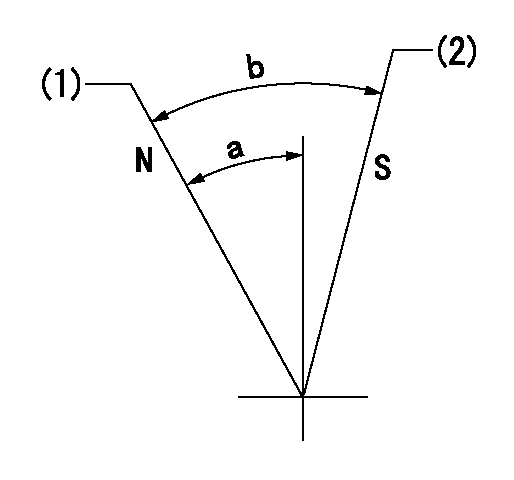
Speed control lever angle

N:Pump normal
S:Stop the pump.
(1)Rack position = aa
(2)Rack position bb
----------
aa=20mm bb=1mm
----------
a=27deg+-5deg b=37deg+-5deg
----------
aa=20mm bb=1mm
----------
a=27deg+-5deg b=37deg+-5deg
0000000901

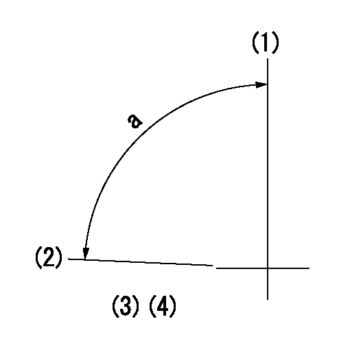
(1)Pump vertical direction
(2)Position of the coupling's key groove at the beginning of injection of the No. 8 cylinder.
(3)Pre-stroke: aa
(4)-
----------
aa=6.4+-0.03mm
----------
a=(85deg)
----------
aa=6.4+-0.03mm
----------
a=(85deg)
0000001501

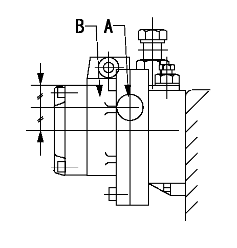
A:Sealing position
B:Pre-stroke actuator
1. When installing the pre-stroke actuator on the pump, first tighten the installation bolts loosely, then move the actuator fully counterclockwise (viewed from the drive side).
Temporary tightening torque: 1 - 1.5 N.m (0.1 - 0.15 kgf.m)
2. Move the actuator in the clockwise direction when viewed from the drive side, and adjust so that it becomes the adjustment point of the adjustment value. Then tighten it.
Tightening torque: 7^9 N.m (0.7^0.9 kgf.m)
3. After prestroke actuator installation adjustment, simultaneously stamp both the actuator side and housing side.
----------
----------
----------
----------
0000001701

(PWM) Pulse width modulation (%)
(R) Rack position (mm)
Rack sensor output characteristics
1. Rack limit adjustment
(1)Measure the rack position R2 for PWM a2%.
(2)Confirm that it is within the range R2 = 15+-1 mm.
(3)Measure the rack position R1 at PWM a %.
(4)Confirm that it is within the range R2 - R1 = 10+-0.1 mm.
2. Check the limp home operation.
(1)Move the switch box's limp home switch to the limp home side.
(2)Confirm rack position L1 (mm ) and L2 (mm) for PWM in the above table.
3. Check the pull down operation.
(1)Confirm that the rack position is 19 mm at PWM B%.
(2)In the conditions described in the above table, move the switch box's pull down switch to the pull down side and confirm that the rack position momentarily becomes 1 mm or less.
----------
a1=16.25 % a2=72.5 % L1=1-- mm L2=19++mm A=5 % B=95 %
----------
----------
a1=16.25 % a2=72.5 % L1=1-- mm L2=19++mm A=5 % B=95 %
----------
Information:
Lubrication For A Rebuilt Engine
It is very important for a rebuilt engine to have "adequate" (needed) lubrication during the first seconds of operation. A "dry start" (without needed lubrication) on a rebuilt engine can cause bearing damage.When an engine is rebuilt with new parts, oil is put on each part as it is installed This is generally enough lubrication for engine start-up. However, this lubrication may not be enough or may be lost if the rebuilt engine is place in storage for any length of time.When a factory assembled short block assembly is installed, the oil used at the factory has to give this needed lubrication. However, the factory oil application can flow off the parts in a short block during storage or shipment. As a result the parts in a rebuit engine will not have "adequate" lubrication start-up.To prevent the possibility of a "dry start" and bearing damage during the first seconds of running, use the 1P540; Flow Checking Tool Group, and Shop air pressure to pressure lubricate (fill the main oil passage with oil under pressure) all rebuilt engines.Procedure for Pressure Lubrication
1. Clean the tank of the 1P540 Flow Checking Tool Group thoroughly, and set the pressure regulator to 35 5 psi (240 35 kPa).
Air pressure should not be more than 50 psi (345 kPa) at any time.
2. Put approximately one gallon of engine oil in the tank.
PRESSURE LUBRICATION (Using the 1P540 Flow Checking Tool Group)3. Connect the tools to the engine as shown. The tap shown is connected to the main oil passage.4. Add air pressure to the tank, with the regulator set at 35 5 psi (240 35 kPa). Although the tank does have a hand pump, it is difficult to get enough air pressure to do the job with the hand pump. Therefore, use of shop air is recommended.5. Let the one gallon of engine oil flow into the oil passage under pressure.When filling the crankcase, put in one gallon of oil less than the recommendation in the Lubrication and Maintenance Guides, if engine has received this pressure lubrication application. Also if the engine is not going to be used for a long time, do the above procedure again before the first starting.If shop air is not available for charging the tank, the hand pump may be used to get the minimum required pressure.
Do not use the same 1P540 Flow Checking Tool Group for both "pressure lubrication application" and for checking fuel flow. Incorrect cleaning is probable if the tool is used for both fuel and lube oil. Even a minute amount of dirt in the fuel system can cause fuel nozzle failure.
Dynamometer Test Precaution
To avoid possible engine damage while testing on a dynamometer, the thermostats must be installed and the shunt line connected as shown.
SHUNT LINE CONNECTED TO ENGINEInitial Operation After Engine Reconditioning
The quality of oil control components used in Caterpillar engines is such that, following engine reconditioning (with Caterpillar Service Parts), only an initial operational check is
Have questions with 108821-0214?
Group cross 108821-0214 ZEXEL
Nissan-Diesel
108821-0214
9 400 612 148
16801ND001
INJECTION-PUMP ASSEMBLY
RH8
RH8