Information injection-pump assembly
BOSCH
9 400 611 776
9400611776
ZEXEL
108821-0212
1088210212
NISSAN-DIESEL
1680197673
1680197673

Rating:
Service parts 108821-0212 INJECTION-PUMP ASSEMBLY:
1.
_
7.
COUPLING PLATE
9.
_
11.
Nozzle and Holder
16600-97200
12.
Open Pre:MPa(Kqf/cm2)
15.7{160}/18.6{190}
14.
NOZZLE
Include in #1:
108821-0212
as INJECTION-PUMP ASSEMBLY
Cross reference number
BOSCH
9 400 611 776
9400611776
ZEXEL
108821-0212
1088210212
NISSAN-DIESEL
1680197673
1680197673
Zexel num
Bosch num
Firm num
Name
Calibration Data:
Adjustment conditions
Test oil
1404 Test oil ISO4113 or {SAEJ967d}
1404 Test oil ISO4113 or {SAEJ967d}
Test oil temperature
degC
40
40
45
Nozzle and nozzle holder
105780-8250
Bosch type code
1 688 901 101
Nozzle
105780-0120
Bosch type code
1 688 901 990
Nozzle holder
105780-2190
Opening pressure
MPa
20.7
Opening pressure
kgf/cm2
211
Injection pipe
Outer diameter - inner diameter - length (mm) mm 8-3-600
Outer diameter - inner diameter - length (mm) mm 8-3-600
Overflow valve
134424-4120
Overflow valve opening pressure
kPa
255
221
289
Overflow valve opening pressure
kgf/cm2
2.6
2.25
2.95
Tester oil delivery pressure
kPa
255
255
255
Tester oil delivery pressure
kgf/cm2
2.6
2.6
2.6
RED4 control unit part number
407915-0
590
RED4 rack sensor specifications
mm
19
PS/ACT control unit part no.
407980-2
24*
Digi switch no.
41
Direction of rotation (viewed from drive side)
Right R
Right R
Injection timing adjustment
Direction of rotation (viewed from drive side)
Right R
Right R
Injection order
8-7-5-4-
3-6-2-1
Pre-stroke
mm
6.4
6.37
6.43
Beginning of injection position
Governor side NO.1
Governor side NO.1
Difference between angles 1
Cal 8-7 deg. 45 44.75 45.25
Cal 8-7 deg. 45 44.75 45.25
Difference between angles 2
Cal 8-5 deg. 90 89.75 90.25
Cal 8-5 deg. 90 89.75 90.25
Difference between angles 3
Cal 8-4 deg. 135 134.75 135.25
Cal 8-4 deg. 135 134.75 135.25
Difference between angles 4
Cal 8-3 deg. 180 179.75 180.25
Cal 8-3 deg. 180 179.75 180.25
Difference between angles 5
Cal 8-6 deg. 225 224.75 225.25
Cal 8-6 deg. 225 224.75 225.25
Difference between angles 6
Cal 8-2 deg. 270 269.75 270.25
Cal 8-2 deg. 270 269.75 270.25
Difference between angles 7
Cal 8-1 deg. 315 314.75 315.25
Cal 8-1 deg. 315 314.75 315.25
Injection quantity adjustment
Rack position
(12.7)
PWM
%
59.3
Pump speed
r/min
600
600
600
Average injection quantity
mm3/st.
144
142
146
Max. variation between cylinders
%
0
-4
4
Basic
*
PS407980-224*
V
2.2+-0.0
1
PS407980-224*
mm
4+-0.05
Injection quantity adjustment_02
Rack position
(7.4)
PWM
%
29.9+-2.
8
Pump speed
r/min
320
320
320
Average injection quantity
mm3/st.
13.5
11.5
15.5
Max. variation between cylinders
%
0
-10
10
PS407980-224*
V
V1+0.05+
-0.01
PS407980-224*
mm
6.3+-0.0
3
Remarks
Refer to items regarding the pre-stroke actuator
Refer to items regarding the pre-stroke actuator
Governor adjustment
Pump speed
r/min
760--
Advance angle
deg.
0
0
0
Remarks
Start
Start
Governor adjustment_02
Pump speed
r/min
710
Advance angle
deg.
0.5
Governor adjustment_03
Pump speed
r/min
1010
Advance angle
deg.
3
2.5
3.5
Remarks
Finish
Finish
0000001201
Pre-stroke
mm
6.4
6.37
6.43
Remarks
When the timing sleeve is pushed up
When the timing sleeve is pushed up
_02
Connector angle
deg.
11.5
11
12
Remarks
When the eccentric pin is tightened
When the eccentric pin is tightened
_03
Supply voltage
V
24
23.5
24.5
Ambient temperature
degC
23
18
28
Pre-stroke
mm
2.4
2.35
2.45
Output voltage
V
2.95
2.94
2.96
Adjustment
*
_04
Supply voltage
V
24
23.5
24.5
Ambient temperature
degC
23
18
28
Pre-stroke
mm
6.4
6.37
6.43
Output voltage
V
1.2
1
1.4
Confirmation
*
Remarks
Output voltage V1
Output voltage V1
_05
Supply voltage
V
24
23.5
24.5
Ambient temperature
degC
23
18
28
Output voltage
V
3.05
3.05
Confirmation of operating range
*
Test data Ex:
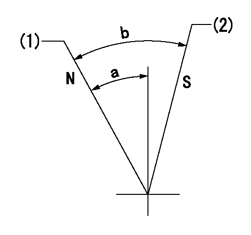
Speed control lever angle

N:Pump normal
S:Stop the pump.
(1)Rack position = aa
(2)Rack position bb
----------
aa=20mm bb=1mm
----------
a=27deg+-5deg b=37deg+-5deg
----------
aa=20mm bb=1mm
----------
a=27deg+-5deg b=37deg+-5deg
0000000901

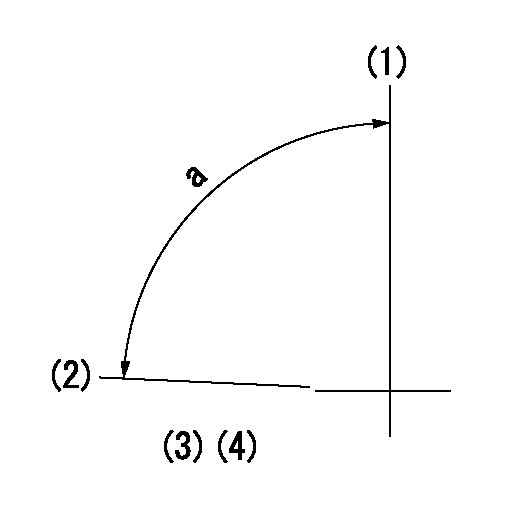
(1)Pump vertical direction
(2)Position of the coupling's key groove at the beginning of injection of the No. 8 cylinder.
(3)Pre-stroke: aa
(4)-
----------
aa=6.4+-0.03mm
----------
a=(85deg)
----------
aa=6.4+-0.03mm
----------
a=(85deg)
0000001501

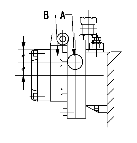
A:Sealing position
B:Pre-stroke actuator
1. When installing the pre-stroke actuator on the pump, first tighten the installation bolts loosely, then move the actuator fully counterclockwise (viewed from the drive side).
Temporary tightening torque: 1 - 1.5 N.m (0.1 - 0.15 kgf.m)
2. Move the actuator in the clockwise direction when viewed from the drive side, and adjust so that it becomes the adjustment point of the adjustment value. Then tighten it.
Tightening torque: 7^9 N.m (0.7^0.9 kgf.m)
3. After prestroke actuator installation adjustment, simultaneously stamp both the actuator side and housing side.
----------
----------
----------
----------
0000001701

(PWM) Pulse width modulation (%)
(R) Rack position (mm)
Rack sensor output characteristics
1. Rack limit adjustment
(1)Measure the rack position R2 for PWM a2%.
(2)Confirm that it is within the range R2 = 15+-1 mm.
(3)Measure the rack position R1 at PWM a %.
(4)Confirm that it is within the range R2 - R1 = 10+-0.1 mm.
2. Check the limp home operation.
(1)Move the switch box's limp home switch to the limp home side.
(2)Confirm rack position L1 (mm ) and L2 (mm) for PWM in the above table.
3. Check the pull down operation.
(1)Confirm that the rack position is 19 mm at PWM B%.
(2)In the conditions described in the above table, move the switch box's pull down switch to the pull down side and confirm that the rack position momentarily becomes 1 mm or less.
----------
a1=16.25 % a2=72.5 % L1=1-- mm L2=19++mm A=5 % B=95 %
----------
----------
a1=16.25 % a2=72.5 % L1=1-- mm L2=19++mm A=5 % B=95 %
----------
Information:
Crankshaft Grinding Specifications
The dimensions and finish for grinding crankshafts are as follows:Diameter (A) for connecting rod bearing journals is;.010 in. (0.25 mm) Undersize ... 2.7396 .0006 in.(69.586 0.015 mm).020 in. (0.51 mm) Undersize ... 2.7296 .0006 in.(69.332 0.015 mm).050 in. (1.27 mm) Undersize ... 2.6996 .0006 in.(68.570 0.015 mm)Surface finish must be 10 micro inches (0.25 micrometers) or less.Radius (B) must be .100 .010 in. (2.54 0.25 mm).Surface finish must be 63 micro inches (1.6 micrometers) or less.The radius must blend smoothly with the newly machined journals.
DIMENSIONS FOR GRINDING
A. Diameter of connecting rod bearing journals. B. Radius on connecting rod bearing journals. C. Width to grind journals for the connecting rods. D. Diameter of main bearing journals. E. Radius on main bearing journals. F. Width to grind journals for the main bearings.Width (C) is 2.314 .003 in. (58.77 0.08 mm)Diameter (D) for main bearing journals is:.010 in. (0.25 mm) Undersize ... 3.4895 .0006 in.(88.633 0.015 mm).020 in. (0.51 mm) Undersize ... 3.4795 .0006 in.(88.379 0.015 mm).050 in. (1.27 mm) Undersize ... 3.4495 .0006 in.(87.617 0.015 mm)Surface finish must be 10 micro inches (0.25 micrometers) or less.Radius (E) must be .095 .010 in. (2.41 0.25 mm)Surface finish must be 63 micro inches (1.6 micrometers) or less.The radius must blend smoothly with the newly machined journals.Width (F) is 1.258 .002 in. (31.95 0.05 mm) for number 4 main bearing journal. Surface finish on the thrust faces of the number 4 main must be 18 micro inches (0.45 micrometers) or less.Width (F) is 1.268 + .020 - .010 in. (32.21 + 0.51 - 0.25 mm) for number 2, 3, and 5 main bearing journals.There is no width (F) for number 1 main bearing journal.When grinding a crankshaft, no material can be removed from the crankshaft webs or counterweights.Crankshaft Gear Removal
Remove the gear using an 8B7548 Push Puller, 8B7551 Bearing Pulling Attachment, 8B75621 Step Plate, and 8H684 Ratchet Box Wrench.
PULLING CRANKSHAFT GEARThe 1P820 Hydraulic Puller Group can also be used to pull gear from crankshaft. Tools required are 1P820 Hydraulic Puller Group, 8B7551 Bearing Pulling Attachment, 8B7549 Puller legs (two), 8B7561 Step Plate, 3H465 Plate (four), 1B4207 Nut (two), and 5P3100 Pump Group.
USING HYDRAULIC PULLERCrankshaft Gear Installation
1. Install the key in keyway of crankshaft. Remove all burrs from key and keyway inside of crankshaft gear.2. Heat gear to 500°F (260°C) maximum.3. Install gear on crankshaft with timing mark on gear facing front of crankshaft.Crankshaft Front Oil Seal Removal
Remove the crankshaft front pulley. Use the 1P3075 Puller Group to remove the crankshaft front oil seal.
REMOVING FRONT OIL SEAL (Typical Example)Remove Crankshaft Rear Seal And Wear Sleeve
Remove the crankshaft rear oil seal with the 1P3075 Puller Group.
REMOVING REAR OIL SEALInstall a 5P7338 Distorter Ring from the 5P7318 Wear Sleeve Distorter Group, in the rear seal bore.
REMOVING REAR WEAR SLEEVE (Typical Example)Install 5P7312 Distorter between distorter ring and wear sleeve. Turn the distorter until the