Information injection-pump assembly
BOSCH
9 400 619 232
9400619232
ZEXEL
108821-0090
1088210090
NISSAN-DIESEL
1680197608
1680197608
Rating:
Cross reference number
BOSCH
9 400 619 232
9400619232
ZEXEL
108821-0090
1088210090
NISSAN-DIESEL
1680197608
1680197608
Zexel num
Bosch num
Firm num
Name
108821-0090
9 400 619 232
1680197608 NISSAN-DIESEL
INJECTION-PUMP ASSEMBLY
RG8 K
RG8 K
Calibration Data:
Adjustment conditions
Test oil
1404 Test oil ISO4113 or {SAEJ967d}
1404 Test oil ISO4113 or {SAEJ967d}
Test oil temperature
degC
40
40
45
Nozzle and nozzle holder
105780-8250
Bosch type code
1 688 901 101
Nozzle
105780-0120
Bosch type code
1 688 901 990
Nozzle holder
105780-2190
Opening pressure
MPa
20.7
Opening pressure
kgf/cm2
211
Injection pipe
Outer diameter - inner diameter - length (mm) mm 8-3-600
Outer diameter - inner diameter - length (mm) mm 8-3-600
Overflow valve
134424-4120
Overflow valve opening pressure
kPa
255
221
289
Overflow valve opening pressure
kgf/cm2
2.6
2.25
2.95
Tester oil delivery pressure
kPa
255
255
255
Tester oil delivery pressure
kgf/cm2
2.6
2.6
2.6
RED4 control unit part number
407915-0
590
RED4 rack sensor specifications
mm
19
PS/ACT control unit part no.
407980-2
24*
Digi switch no.
41
Direction of rotation (viewed from drive side)
Right R
Right R
Injection timing adjustment
Direction of rotation (viewed from drive side)
Right R
Right R
Injection order
1-8-7-5-
4-3-6-2
Pre-stroke
mm
6.4
6.37
6.43
Beginning of injection position
Governor side NO.1
Governor side NO.1
Difference between angles 1
Cal 1-8 deg. 45 44.75 45.25
Cal 1-8 deg. 45 44.75 45.25
Difference between angles 2
Cal 1-7 deg. 90 89.75 90.25
Cal 1-7 deg. 90 89.75 90.25
Difference between angles 3
Cal 1-5 deg. 135 134.75 135.25
Cal 1-5 deg. 135 134.75 135.25
Difference between angles 4
Cal 1-4 deg. 180 179.75 180.25
Cal 1-4 deg. 180 179.75 180.25
Difference between angles 5
Cal 1-3 deg. 225 224.75 225.25
Cal 1-3 deg. 225 224.75 225.25
Difference between angles 6
Cal 1-6 deg. 270 269.75 270.25
Cal 1-6 deg. 270 269.75 270.25
Difference between angles 7
Cyl.1-2 deg. 315 314.75 315.25
Cyl.1-2 deg. 315 314.75 315.25
Injection quantity adjustment
Rack position
(12.2)
PWM
%
56.8
Pump speed
r/min
600
600
600
Average injection quantity
mm3/st.
131
129
133
Max. variation between cylinders
%
0
-4
4
Basic
*
PS407980-224*
V
2.2+-0.0
1
PS407980-224*
mm
4+-0.05
Injection quantity adjustment_02
Rack position
(7.6)
PWM
%
30.9+-2.
8
Pump speed
r/min
295
295
295
Average injection quantity
mm3/st.
16.5
14.5
18.5
Max. variation between cylinders
%
0
-10
10
PS407980-224*
V
V1+0.05+
-0.01
PS407980-224*
mm
6.3+-0.0
3
Remarks
Refer to items regarding the pre-stroke actuator
Refer to items regarding the pre-stroke actuator
Governor adjustment
Pump speed
r/min
750--
Advance angle
deg.
0
0
0
Remarks
Start
Start
Governor adjustment_02
Pump speed
r/min
700
Advance angle
deg.
0.5
Governor adjustment_03
Pump speed
r/min
1000
Advance angle
deg.
3
2.5
3.5
Remarks
Finish
Finish
0000001201
Pre-stroke
mm
6.4
6.37
6.43
Remarks
When the timing sleeve is pushed up
When the timing sleeve is pushed up
_02
Connector angle
deg.
11.5
11
12
Remarks
When the eccentric pin is tightened
When the eccentric pin is tightened
_03
Supply voltage
V
24
23.5
24.5
Ambient temperature
degC
23
18
28
Pre-stroke
mm
2.4
2.35
2.45
Output voltage
V
2.95
2.94
2.96
Adjustment
*
_04
Supply voltage
V
24
23.5
24.5
Ambient temperature
degC
23
18
28
Pre-stroke
mm
6.4
6.37
6.43
Output voltage
V
1.2
1
1.4
Confirmation
*
Remarks
Output voltage V1
Output voltage V1
_05
Supply voltage
V
24
23.5
24.5
Ambient temperature
degC
23
18
28
Output voltage
V
3.05
3.05
Confirmation of operating range
*
Test data Ex:
Speed control lever angle
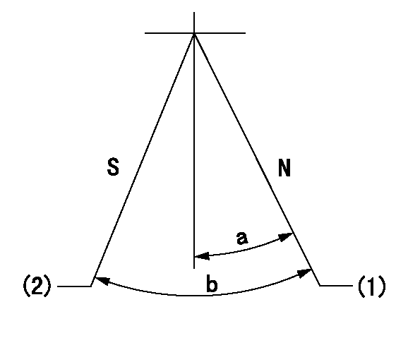
N:Pump normal
S:Stop the pump.
(1)Rack position = aa
(2)Rack position bb
----------
aa=20mm bb=1mm
----------
a=20deg+-5deg b=37deg+-5deg
----------
aa=20mm bb=1mm
----------
a=20deg+-5deg b=37deg+-5deg
0000000901

(1)Pump vertical direction
(2)Position of the coupling's key groove at the beginning of injection of the No. 8 cylinder.
(3)Pre-stroke: aa
(4)-
----------
aa=6.4+-0.03mm
----------
a=(80deg)
----------
aa=6.4+-0.03mm
----------
a=(80deg)
0000001501

A:Sealing position
B:Pre-stroke actuator
1. When installing the pre-stroke actuator on the pump, first tighten the installation bolts loosely, then move the actuator fully counterclockwise (viewed from the drive side).
Temporary tightening torque: 1 - 1.5 N.m (0.1 - 0.15 kgf.m)
2. Move the actuator in the clockwise direction when viewed from the drive side, and adjust so that it becomes the adjustment point of the adjustment value. Then tighten it.
Tightening torque: 7^9 N.m (0.7^0.9 kgf.m)
3. After prestroke actuator installation adjustment, simultaneously stamp both the actuator side and housing side.
----------
----------
----------
----------
0000001701

(PWM) Pulse width modulation (%)
(R) Rack position (mm)
Rack sensor output characteristics
1. Rack limit adjustment
(1)Measure the rack position R2 for PWM a2%.
(2)Confirm that it is within the range R2 = 15+-1 mm.
(3)Measure the rack position R1 at PWM a %.
(4)Confirm that it is within the range R2 - R1 = 10+-0.1 mm.
2. Check the limp home operation.
(1)Move the switch box's limp home switch to the limp home side.
(2)Confirm rack position L1 (mm ) and L2 (mm) for PWM in the above table.
3. Check the pull down operation.
(1)Confirm that the rack position is 19 mm at PWM B%.
(2)In the conditions described in the above table, move the switch box's pull down switch to the pull down side and confirm that the rack position momentarily becomes 1 mm or less.
----------
a1=16.25% a2=72.5% L1=1--mm L2=19++mm A=5% B=95%
----------
----------
a1=16.25% a2=72.5% L1=1--mm L2=19++mm A=5% B=95%
----------
Information:
2. Locate wire 405-GY on the main cab harness near the connector exiting the cab wall on the right hand side, as shown by arrow.Cut this wire close to the connector. Splice it and the wire just assembled using an 8S4626 Splice. Be sure to splice to the portion of the wire that goes into the cab harness.3. Connect the 7N9738 Housing to the two pin connector on the 8X9862 Harness Assembly (housing containing 405-GY). Clip with a 3T3048 Clip Assembly.Installation of Ether (Chassis) Wiring Harness
The ether chassis harness for MPPS is different than the one called out in the AEIS Special Instruction.* Substitute 8X8468 Harness Assembly for 8X7653 Harness Assembly on the 785 Trucks.* Substitute 8X8467 Harness Assembly for 8X7652 Harness Assembly on the 789 Trucks.Follow the installation procedure outlined in the AEIS Special Instruction for the Ether Chassis Harness Assembly. Be sure to use the 8X8466 Wire Assembly for the 785 Trucks or the 8X8429 Wire Assembly for the 789 Trucks. This is the new harness code plug required with MPPS.Installation of 8X8469 Ether (Engine) Wiring Harness
The 8X7106 Engine Harness on the AEIS is replaced with 8X8469 Harness Assembly.Follow the installation procedure outlined in the AEIS Special Instruction for the 8X7106 Harness Assembly. In addition, the following steps need to be performed. 1. Route the end of the harness with the 8T8732 Receptacle to the 3E3530 Electronic Control Group (oil pressure sensor) installed at the right rear of the engine as shown.2. Connect the three pin receptacle to the connector on the 3E3530 Electronic Control Group (2) and clip into the 9X3495 Clip Assembly (7) installed earlier. Use 3S2093 Straps (8) to loosely secure the harness to the top rear of the engine as shown.3. Remove the 8W3048 Harness Assembly that is connected to the remaining 6T7663 Oil Pressure Switch (9) and was connected to the 6T7663 Oil Pressure Switch (9) that was removed.4. Connect an 8X8337 Harness Assembly (10) to the one remaining oil pressure switch and reconnect to the engine harness. Clip with the existing clip. DO NOT tighten the straps or clips until all new wiring harnesses have been installed so any repositioning or adjustments can be made as necessary.Checking the Automatic Ether Injection System
* The system check-out will be same as for the AEIS with the following change: "A5" harness code on the 785 (indicates 3512 application) or "A6" harness code on the 789 (indicates 3516 application) for two seconds.Retrofit to an Existing AEIS System
Necessary Parts
Installation of 3E3778 Ether Control Group
The 3E3778 Control Group is required for the MPPS System.Check the electronic control box installed with the AEIS to see if it is a 3E3778 or a 9X5303 Control Group. If a 9X5303 control Group is installed, replace it with 3E3778 Control Group and 3E3779 Film.Follow the "Installation of 9X5303 Ether Control Group" instructions outlined in the AEIS installation Special Instruction, SEHS9293. Be sure to install the 8X8398 Wire Assembly between the control and mounting plate. If an MPPS identification film is
Have questions with 108821-0090?
Group cross 108821-0090 ZEXEL
Nissan-Diesel
Nissan-Diesel
108821-0090
9 400 619 232
1680197608
INJECTION-PUMP ASSEMBLY
RG8
RG8