Information injection-pump assembly
BOSCH
9 400 612 516
9400612516
ZEXEL
108622-4070
1086224070
Rating:
Service parts 108622-4070 INJECTION-PUMP ASSEMBLY:
1.
_
5.
AUTOM. ADVANCE MECHANIS
9.
_
11.
Nozzle and Holder
12.
Open Pre:MPa(Kqf/cm2)
14.
NOZZLE
15.
NOZZLE SET
Include in #1:
108622-4070
as INJECTION-PUMP ASSEMBLY
Cross reference number
BOSCH
9 400 612 516
9400612516
ZEXEL
108622-4070
1086224070
Zexel num
Bosch num
Firm num
Name
9 400 612 516
DAEWOO
INJECTION-PUMP ASSEMBLY
DE12TIS K 14CJ INJECTION PUMP ASSY TICS HD-TI6M TICS
DE12TIS K 14CJ INJECTION PUMP ASSY TICS HD-TI6M TICS
Calibration Data:
Adjustment conditions
Test oil
1404 Test oil ISO4113 or {SAEJ967d}
1404 Test oil ISO4113 or {SAEJ967d}
Test oil temperature
degC
40
40
45
Nozzle and nozzle holder
105780-8250
Bosch type code
1 688 901 101
Nozzle
105780-0120
Bosch type code
1 688 901 990
Nozzle holder
105780-2190
Opening pressure
MPa
20.7
Opening pressure
kgf/cm2
211
Injection pipe
Outer diameter - inner diameter - length (mm) mm 8-3-600
Outer diameter - inner diameter - length (mm) mm 8-3-600
Overflow valve
134424-4120
Overflow valve opening pressure
kPa
255
221
289
Overflow valve opening pressure
kgf/cm2
2.6
2.25
2.95
Tester oil delivery pressure
kPa
255
255
255
Tester oil delivery pressure
kgf/cm2
2.6
2.6
2.6
PS/ACT control unit part no.
407980-2
24*
Digi switch no.
31
Direction of rotation (viewed from drive side)
Right R
Right R
Injection timing adjustment
Direction of rotation (viewed from drive side)
Right R
Right R
Injection order
1-5-3-6-
2-4
Pre-stroke
mm
6.4
6.37
6.43
Beginning of injection position
Governor side NO.1
Governor side NO.1
Difference between angles 1
Cal 1-5 deg. 60 59.75 60.25
Cal 1-5 deg. 60 59.75 60.25
Difference between angles 2
Cal 1-3 deg. 120 119.75 120.25
Cal 1-3 deg. 120 119.75 120.25
Difference between angles 3
Cal 1-6 deg. 180 179.75 180.25
Cal 1-6 deg. 180 179.75 180.25
Difference between angles 4
Cyl.1-2 deg. 240 239.75 240.25
Cyl.1-2 deg. 240 239.75 240.25
Difference between angles 5
Cal 1-4 deg. 300 299.75 300.25
Cal 1-4 deg. 300 299.75 300.25
Injection quantity adjustment
Adjusting point
-
Rack position
15.4
Pump speed
r/min
630
630
630
Average injection quantity
mm3/st.
159.5
156.5
162.5
Max. variation between cylinders
%
0
-2
2
Basic
*
Fixing the rack
*
PS407980-224*
V
2.45+-0.
01
PS407980-224*
mm
4+-0.05
Standard for adjustment of the maximum variation between cylinders
*
Injection quantity adjustment_02
Adjusting point
Z
Rack position
8.9+-0.5
Pump speed
r/min
445
445
445
Average injection quantity
mm3/st.
13.5
12
15
Max. variation between cylinders
%
0
-15
15
Fixing the rack
*
PS407980-224*
V
V1+0.05+
-0.01
PS407980-224*
mm
6.3+-0.0
3
Standard for adjustment of the maximum variation between cylinders
*
Remarks
Refer to items regarding the pre-stroke actuator
Refer to items regarding the pre-stroke actuator
Injection quantity adjustment_03
Adjusting point
A
Rack position
R1(15.4)
Pump speed
r/min
630
630
630
Average injection quantity
mm3/st.
159.5
157.5
161.5
Basic
*
Fixing the lever
*
Boost pressure
kPa
99.3
99.3
Boost pressure
mmHg
745
745
PS407980-224*
V
2.45+-0.
01
PS407980-224*
mm
4+-0.05
Injection quantity adjustment_04
Adjusting point
B
Rack position
(R1+1.25
)
Pump speed
r/min
1050
1050
1050
Average injection quantity
mm3/st.
145.5
139.5
151.5
Fixing the lever
*
Boost pressure
kPa
99.3
99.3
Boost pressure
mmHg
745
745
PS407980-224*
V
2.45+-0.
01
PS407980-224*
mm
4+-0.05
Boost compensator adjustment
Pump speed
r/min
250
250
250
Rack position
R2-3.6
Boost pressure
kPa
10.7
9.4
12
Boost pressure
mmHg
80
70
90
Boost compensator adjustment_02
Pump speed
r/min
250
250
250
Rack position
R2(R1+0.
2)
Boost pressure
kPa
86
86
86
Boost pressure
mmHg
645
645
645
0000001601
Pre-stroke
mm
6.4
6.37
6.43
Remarks
When the timing sleeve is pushed up
When the timing sleeve is pushed up
_02
Connector angle
deg.
8.5
8
9
Remarks
When the eccentric pin is tightened
When the eccentric pin is tightened
_03
Supply voltage
V
24
23.5
24.5
Ambient temperature
degC
23
18
28
Pre-stroke
mm
4
3.95
4.05
Output voltage
V
2.45
2.44
2.46
Adjustment
*
_04
Supply voltage
V
24
23.5
24.5
Ambient temperature
degC
23
18
28
Pre-stroke
mm
6.4
6.37
6.43
Output voltage
V
1.2
1
1.4
Confirmation
*
Remarks
Output voltage V1
Output voltage V1
_05
Supply voltage
V
24
23.5
24.5
Ambient temperature
degC
23
18
28
Pre-stroke
mm
3.4
Output voltage
V
3
2.98
3
Confirmation
*
_06
Supply voltage
V
24
23.5
24.5
Ambient temperature
degC
23
18
28
Output voltage
V
3.05
3.05
Confirmation of operating range
*
Test data Ex:
Governor adjustment
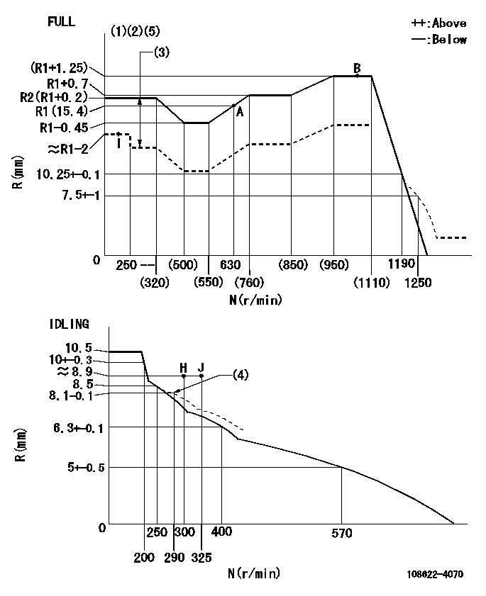
N:Pump speed
R:Rack position (mm)
(1)Torque cam stamping: T1
(2)Tolerance for racks not indicated: +-0.05mm.
(3)Boost compensator stroke: BCL
(4)Damper spring setting
(5)Microswitch adjustment unnecessary (deliver with adjusting bolt fully backed off).
----------
T1=AG63 BCL=3.6+-0.1mm
----------
----------
T1=AG63 BCL=3.6+-0.1mm
----------
Speed control lever angle
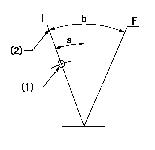
F:Full speed
I:Idle
(1)Use the hole at R = aa
(2)Stopper bolt set position 'H'
----------
aa=70.3mm
----------
a=10.5deg+-5deg b=38deg+-3deg
----------
aa=70.3mm
----------
a=10.5deg+-5deg b=38deg+-3deg
Stop lever angle
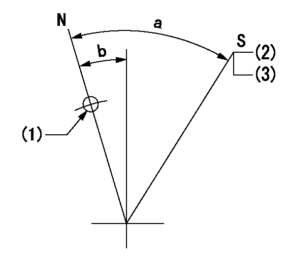
N:Pump normal
S:Stop the pump.
(1)Use the hole at R = aa
(2)Speed = bb, rack position = cc
(3)Set the stopper screw. (After setting, apply red paint.)
----------
aa=40mm bb=0r/min cc=1.5+-0.3mm
----------
a=44deg+-5deg b=20deg+-5deg
----------
aa=40mm bb=0r/min cc=1.5+-0.3mm
----------
a=44deg+-5deg b=20deg+-5deg
0000001301

(1)Pump vertical direction
(2)Coupling's key groove position at No 1 cylinder's beginning of injection
(3)Pre-stroke: aa
(4)-
----------
aa=6.4+-0.03mm
----------
a=(70deg)
----------
aa=6.4+-0.03mm
----------
a=(70deg)
0000001901

A:Sealing position
B:Pre-stroke actuator
1. When installing the pre-stroke actuator on the pump, first tighten the installation bolts loosely, then move the actuator fully counterclockwise (viewed from the drive side).
Temporary tightening torque: 1 - 1.5 N.m (0.1 - 0.15 kgf.m)
2. Move the actuator in the clockwise direction when viewed from the drive side, and adjust so that it becomes the adjustment point of the adjustment value. Then tighten it.
Tightening torque: 7^9 N.m (0.7^0.9 kgf.m)
3. After prestroke actuator installation adjustment, simultaneously stamp both the actuator side and housing side.
----------
----------
----------
----------
0000002201 RACK SENSOR
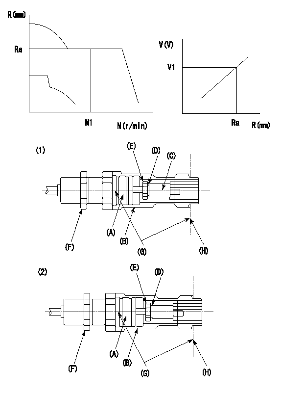
G:Red paint
H:Pump end face
P/N: part number of suitable shim
(1)Threaded type rack block
(2)Welded type rack block
Rack sensor adjustment
1. Threaded type rack sensor (-5*20, P type, no TICS rack limit).
(1)Screw in the bobbin (A) until it contacts the joint (B).
(2)Fix the pump lever.
(3)At speed N1 and rack position Ra, adjust the amount that the bobbin is screwed in so that the amp's output voltage is V1.
(4)Fix using the nut (F).
(5)Affix the caution plate to the upper part of the joint (B).
(6)Apply (G) at two places.
Connecting part between the joint (B) and the nut (F)
Connecting part between the end surface of the pump (H) and the joint (B)
2. Range for screw-in adjustment between the bobbin (A) and the joint (B) is 9 threads.
Screw in to the end from (the position where the bobbin (A) is rotated 9 turns).
Speed N1, rack position Ra, output voltage V1, rack sensor supply voltage 5+-0.01 (V)
----------
Ra=(R1(15.4)+1.25)mm N1=1050r/min V1=3+-0.01V
----------
----------
Ra=(R1(15.4)+1.25)mm N1=1050r/min V1=3+-0.01V
----------
Information:
When using an external electrical source to start your engine: turn the START switch off, remove the key, and turn off all electrical accessories before attaching cables.When using jumper cables always connect the POSITIVE (+) cable to the POSITIVE (+) terminal of the battery connected to the starter solenoid. Connect the NEGATIVE (-) cable from the external source to the starter NEGATIVE (-) terminal. If not equipped with a starter NEGATIVE terminal, connect to the engine block.Do not reverse the battery cables. The alternator can be damaged. Attach the ground cable last and remove first.
1. Connect one end of the cable to the POSITIVE (+) terminal of the battery being started. Connect the other end to the POSITIVE (+) terminal of the power source.2. Connect one of the other cable to the NEGATIVE (-) terminal of the power source. Connect the other end to starter NEGATIVE (-) terminal or to the engine block. This prevents potential sparks from igniting combustible gases produced by some batteries.3. Start the engine.4. After the engine starts, disconnect the cable from the starter NEGATIVE (-) terminal or engine block. Disconnect the other end from the NEGATIVE (-) terminal of the power source.5. Disconnect the cable from the POSITIVE (+) terminal of the battery on the engine being started. Disconnect the cable from the POSITIVE (+) terminal of the power source.Air Starting
For good life of the air starting motor, the air supply must be free of dirt and water. A lubricator must be used with the starting system. Use non detergent 10W engine oil for temperatures that are greater than 0°C (32°F) or use air tool oil for lower temperatures.1. Open and close the drain valve on the bottom of the air tank to drain condensation and oil carryover.2. Check the air supply pressure. The air starting motor requires a minimum of 690 kPa (100 psi) air pressure to operate properly. The maximum air pressure must not exceed 1550 kPa (225 psi). The normal air pressure will be 758 to 965 kPa (110 to 140 psi).
Air Starter showing Air Valve (1) and Lubricator Bowl (2)3. Check the oil level in the lubricator bowl (2). Keep the bowl at least half full and add lubricant if necessary.4. Push the air valve (1) or the engine start button to crank the engine. Release the valve or button as soon as the engine starts.Cold Weather Starting Aids
Personal injury or death can result from using ether.Personal injury or property damage can result from alcohol or starting fluids. Alcohol or starting fluids are highly flammable and toxic and if improperly stored could result in injury or property damage.When using starting fluid, follow the manufacturer's instructions carefully. Use ether sparingly and spray it only while cranking the engine.Failure to follow these instructions could result in an explosion and/or fire and possible personal injury.
Excessive ether can cause piston and ring damage. Use ether for cold starting purposes only. Do not use excessive starting fluid during starting or after the engine is