Information injection-pump assembly
ZEXEL
108622-3890
1086223890
HINO
220401872A
220401872a

Rating:
Cross reference number
ZEXEL
108622-3890
1086223890
HINO
220401872A
220401872a
Zexel num
Bosch num
Firm num
Name
Calibration Data:
Adjustment conditions
Test oil
1404 Test oil ISO4113 or {SAEJ967d}
1404 Test oil ISO4113 or {SAEJ967d}
Test oil temperature
degC
40
40
45
Nozzle and nozzle holder
105780-8250
Bosch type code
1 688 901 101
Nozzle
105780-0120
Bosch type code
1 688 901 990
Nozzle holder
105780-2190
Opening pressure
MPa
20.7
Opening pressure
kgf/cm2
211
Injection pipe
Outer diameter - inner diameter - length (mm) mm 8-3-600
Outer diameter - inner diameter - length (mm) mm 8-3-600
Overflow valve
134424-4120
Overflow valve opening pressure
kPa
255
221
289
Overflow valve opening pressure
kgf/cm2
2.6
2.25
2.95
Tester oil delivery pressure
kPa
255
255
255
Tester oil delivery pressure
kgf/cm2
2.6
2.6
2.6
RED3 control unit part number
407910-3
960
RED3 rack sensor specifications
mm
19
PS/ACT control unit part no.
407980-2
24*
Digi switch no.
33
Direction of rotation (viewed from drive side)
Left L
Left L
Injection timing adjustment
Direction of rotation (viewed from drive side)
Left L
Left L
Injection order
1-4-2-6-
3-5
Pre-stroke
mm
6.4
6.37
6.43
Beginning of injection position
Drive side NO.1
Drive side NO.1
Difference between angles 1
Cal 1-4 deg. 60 59.75 60.25
Cal 1-4 deg. 60 59.75 60.25
Difference between angles 2
Cyl.1-2 deg. 120 119.75 120.25
Cyl.1-2 deg. 120 119.75 120.25
Difference between angles 3
Cal 1-6 deg. 180 179.75 180.25
Cal 1-6 deg. 180 179.75 180.25
Difference between angles 4
Cal 1-3 deg. 240 239.75 240.25
Cal 1-3 deg. 240 239.75 240.25
Difference between angles 5
Cal 1-5 deg. 300 299.75 300.25
Cal 1-5 deg. 300 299.75 300.25
Injection quantity adjustment
Rack position
(16.9)
Vist
V
1.32
1.32
1.32
Pump speed
r/min
700
700
700
Average injection quantity
mm3/st.
252
250
254
Max. variation between cylinders
%
0
-2
2
Basic
*
PS407980-224*
V
2.2+-0.0
1
PS407980-224*
mm
4+-0.05
Injection quantity adjustment_02
Rack position
(6.4)
Vist
V
2.9
2.8
3
Pump speed
r/min
425
425
425
Average injection quantity
mm3/st.
16.5
15.5
17.5
Max. variation between cylinders
%
0
-15
15
PS407980-224*
V
V1+0.05+
-0.01
PS407980-224*
mm
6.3+-0.0
3
Remarks
Refer to items regarding the pre-stroke actuator
Refer to items regarding the pre-stroke actuator
0000001201
Pre-stroke
mm
6.4
6.37
6.43
Remarks
When the timing sleeve is pushed up
When the timing sleeve is pushed up
_02
Connector angle
deg.
11.5
11
12
Remarks
When the eccentric pin is tightened
When the eccentric pin is tightened
_03
Supply voltage
V
24
23.5
24.5
Ambient temperature
degC
23
18
28
Pre-stroke
mm
2.4
2.35
2.45
Output voltage
V
2.95
2.94
2.96
Adjustment
*
_04
Supply voltage
V
24
23.5
24.5
Ambient temperature
degC
23
18
28
Pre-stroke
mm
6.4
6.37
6.43
Output voltage
V
1.2
1
1.4
Confirmation
*
Remarks
Output voltage V1
Output voltage V1
_05
Supply voltage
V
24
23.5
24.5
Ambient temperature
degC
23
18
28
Output voltage
V
3.05
3.05
Confirmation of operating range
*
Test data Ex:
Speed control lever angle
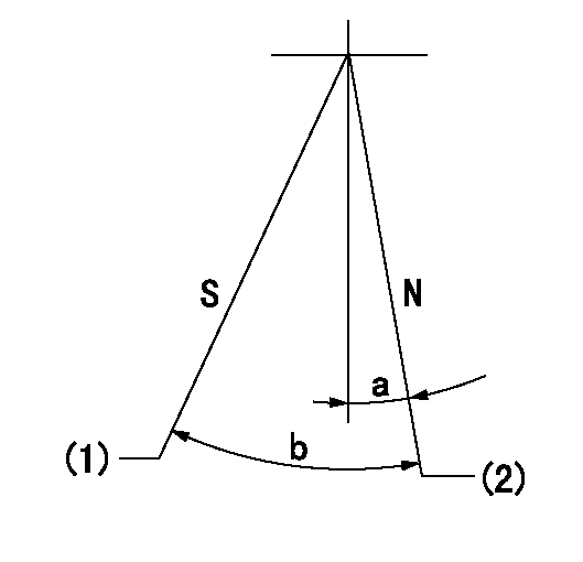
N:Pump normal
S:Stop the pump.
(1)Rack position = aa
(2)Rack position bb
----------
aa=1mm bb=18.5+-0.2mm
----------
a=0deg+-5deg b=34deg+-5deg
----------
aa=1mm bb=18.5+-0.2mm
----------
a=0deg+-5deg b=34deg+-5deg
0000000901

(1)Pump vertical direction
(2)Coupling's key groove position at No 1 cylinder's beginning of injection
(3)Pre-stroke: aa
(4)-
----------
aa=6.4+-0.03mm
----------
a=(20deg)
----------
aa=6.4+-0.03mm
----------
a=(20deg)
0000001501

A:Sealing position
B:Pre-stroke actuator
1. When installing the pre-stroke actuator on the pump, first tighten the installation bolts loosely, then move the actuator fully counterclockwise (viewed from the drive side).
Temporary tightening torque: 1 - 1.5 N.m (0.1 - 0.15 kgf.m)
2. Move the actuator in the clockwise direction when viewed from the drive side, and adjust so that it becomes the adjustment point of the adjustment value. Then tighten it.
Tightening torque: 7^9 N.m (0.7^0.9 kgf.m)
3. After prestroke actuator installation adjustment, simultaneously stamp both the actuator side and housing side.
----------
----------
----------
----------
0000001701

(Rs) rack sensor specifications
(C/U) control unit part number
(V) Rack sensor output voltage
(R) Rack position (mm)
1. Confirming governor output characteristics (rack 19 mm, span 6 mm)
(1)When the output voltages of the rack sensor are V1 and V2, check that the rack positions R1 and R2 in the table above are satisfied.
----------
----------
----------
----------
Information:
You must read and understand the warnings and instructions contained in the Safety section of this manual before performing any operation or maintenance procedures.Before proceeding with Every 50 Hour maintenance, perform all Daily maintenance requirements.Dust Collector
Never run the engine without an air cleaner installed. Never run the engine with a damaged air cleaner. Do not use filter elements with damaged pleats, gaskets or seals. Dirt entering the engine causes premature wear and damage to engine components. Air cleaners prevent airborne debris from entering the engine through the air inlet.
Clean
Typical two stage air cleaner. Individual applications may be different.1. Remove the air cleaner cap (1). Remove the dust collector cup (2).2. Wipe dust collector cup with a clean, dry cloth.3. Install the cup. Install and secure the cap. If equipped with a heavy duty air cleaner: refer to the Heavy Duty Air Cleaner topic in the Daily section of this manual for information about cleaning the dust collector cup.Light Duty Air Cleaner (If Equipped)
Light duty air cleaners are not serviceable (washable). Light duty air cleaners are intended for a 50 service hours of maximum use, or one year, whichever occurs first. However, engines operating in a severe environment may require more frequent air cleaner replacement.Dust conditions vary for different operating environments. Service the air cleaner at regular intervals as determined by the operating environment. Check the air cleaner service indicator (if equipped) daily.Check the air cleaner for cleanliness and damage such as rips and tears. Replace the air cleaner element at the required service interval, or more often as determined by the operating environmental dust conditions. To Replace the Light Duty Air Cleaner Element: 1. Loosen the clamp (2) fastening the air cleaner element (1) to the air inlet, and remove the dirty element and clamp.2. Install the clamp on a new element.3. Install the new element to the air inlet and tighten the clamp.