Information injection-pump assembly
ZEXEL
108622-3880
1086223880
HINO
220401862A
220401862a

Rating:
Cross reference number
ZEXEL
108622-3880
1086223880
HINO
220401862A
220401862a
Zexel num
Bosch num
Firm num
Name
Calibration Data:
Adjustment conditions
Test oil
1404 Test oil ISO4113 or {SAEJ967d}
1404 Test oil ISO4113 or {SAEJ967d}
Test oil temperature
degC
40
40
45
Nozzle and nozzle holder
105780-8250
Bosch type code
1 688 901 101
Nozzle
105780-0120
Bosch type code
1 688 901 990
Nozzle holder
105780-2190
Opening pressure
MPa
20.7
Opening pressure
kgf/cm2
211
Injection pipe
Outer diameter - inner diameter - length (mm) mm 8-3-600
Outer diameter - inner diameter - length (mm) mm 8-3-600
Overflow valve
134424-4120
Overflow valve opening pressure
kPa
255
221
289
Overflow valve opening pressure
kgf/cm2
2.6
2.25
2.95
Tester oil delivery pressure
kPa
255
255
255
Tester oil delivery pressure
kgf/cm2
2.6
2.6
2.6
RED3 control unit part number
407910-3
960
RED3 rack sensor specifications
mm
19
PS/ACT control unit part no.
407980-2
24*
Digi switch no.
33
Direction of rotation (viewed from drive side)
Left L
Left L
Injection timing adjustment
Direction of rotation (viewed from drive side)
Left L
Left L
Injection order
1-4-2-6-
3-5
Pre-stroke
mm
6.4
6.37
6.43
Beginning of injection position
Drive side NO.1
Drive side NO.1
Difference between angles 1
Cal 1-4 deg. 60 59.75 60.25
Cal 1-4 deg. 60 59.75 60.25
Difference between angles 2
Cyl.1-2 deg. 120 119.75 120.25
Cyl.1-2 deg. 120 119.75 120.25
Difference between angles 3
Cal 1-6 deg. 180 179.75 180.25
Cal 1-6 deg. 180 179.75 180.25
Difference between angles 4
Cal 1-3 deg. 240 239.75 240.25
Cal 1-3 deg. 240 239.75 240.25
Difference between angles 5
Cal 1-5 deg. 300 299.75 300.25
Cal 1-5 deg. 300 299.75 300.25
Injection quantity adjustment
Rack position
(15.9)
Vist
V
1.47
1.47
1.47
Pump speed
r/min
700
700
700
Average injection quantity
mm3/st.
226
224
228
Max. variation between cylinders
%
0
-2
2
Basic
*
PS407980-224*
V
2.2+-0.0
1
PS407980-224*
mm
4+-0.05
Injection quantity adjustment_02
Rack position
(6.4)
Vist
V
2.9
2.8
3
Pump speed
r/min
425
425
425
Average injection quantity
mm3/st.
16.5
15.5
17.5
Max. variation between cylinders
%
0
-15
15
PS407980-224*
V
V1+0.05+
-0.01
PS407980-224*
mm
6.3+-0.0
3
Remarks
Refer to items regarding the pre-stroke actuator
Refer to items regarding the pre-stroke actuator
0000001201
Pre-stroke
mm
6.4
6.37
6.43
Remarks
When the timing sleeve is pushed up
When the timing sleeve is pushed up
_02
Connector angle
deg.
11.5
11
12
Remarks
When the eccentric pin is tightened
When the eccentric pin is tightened
_03
Supply voltage
V
24
23.5
24.5
Ambient temperature
degC
23
18
28
Pre-stroke
mm
2.4
2.35
2.45
Output voltage
V
2.95
2.94
2.96
Adjustment
*
_04
Supply voltage
V
24
23.5
24.5
Ambient temperature
degC
23
18
28
Pre-stroke
mm
6.4
6.37
6.43
Output voltage
V
1.2
1
1.4
Confirmation
*
Remarks
Output voltage V1
Output voltage V1
_05
Supply voltage
V
24
23.5
24.5
Ambient temperature
degC
23
18
28
Output voltage
V
3.05
3.05
Confirmation of operating range
*
Test data Ex:
Speed control lever angle
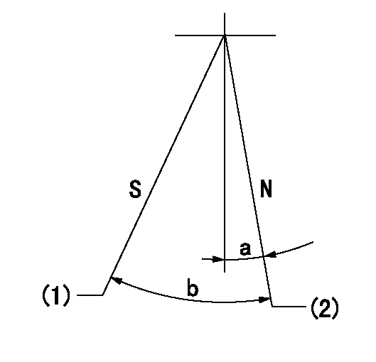
N:Pump normal
S:Stop the pump.
(1)Rack position = aa
(2)Rack position bb
----------
aa=1mm bb=18.5+-0.2mm
----------
a=0deg+-5deg b=34deg+-5deg
----------
aa=1mm bb=18.5+-0.2mm
----------
a=0deg+-5deg b=34deg+-5deg
0000000901

(1)Pump vertical direction
(2)Coupling's key groove position at No 1 cylinder's beginning of injection
(3)Pre-stroke: aa
(4)-
----------
aa=6.4+-0.03mm
----------
a=(20deg)
----------
aa=6.4+-0.03mm
----------
a=(20deg)
0000001501

A:Sealing position
B:Pre-stroke actuator
1. When installing the pre-stroke actuator on the pump, first tighten the installation bolts loosely, then move the actuator fully counterclockwise (viewed from the drive side).
Temporary tightening torque: 1 - 1.5 N.m (0.1 - 0.15 kgf.m)
2. Move the actuator in the clockwise direction when viewed from the drive side, and adjust so that it becomes the adjustment point of the adjustment value. Then tighten it.
Tightening torque: 7^9 N.m (0.7^0.9 kgf.m)
3. After prestroke actuator installation adjustment, simultaneously stamp both the actuator side and housing side.
----------
----------
----------
----------
0000001701

(Rs) rack sensor specifications
(C/U) control unit part number
(V) Rack sensor output voltage
(R) Rack position (mm)
1. Confirming governor output characteristics (rack 19 mm, span 6 mm)
(1)When the output voltages of the rack sensor are V1 and V2, check that the rack positions R1 and R2 in the table above are satisfied.
----------
----------
----------
----------
Information:
Use fuel consumption or service hours, whichever occurs first, to determine maintenance intervals. Experience has shown that maintenance intervals are most accurately scheduled on the basis of fuel consumed rather than service hours.Daily
Walk-Around Inspection - Inspect engine for leaks and loose connections Engine Crankcase - Check oil level Cooling System - Check coolant level Clutch - Check/Adjust/Lubricate Air Starter & Air Tank (if equipped) - Check Engine Air Cleaner - Check service indicator SR4 Generator - Inspect/CheckEvery 1,900 L (500 gal) of Fuel or 50 Service Hours*
Dust Collector - Clean Light Duty Air Cleaner (If Equipped) - ReplaceEvery 4,250 L (1,100 gal) of Fuel or 125 Service Hours*
Clutch - Check/Adjust/Lubricate Generator Space Heaters - CheckEvery 8,500 L (2,200 gal) of Fuel or 250 Service Hours*
Scheduled Oil Sampling (S O S)1 - Obtain Sample Engine Oil and Filter(s)1 - Change Crankcase Breather1 - Clean Engine Valve Lash (Between First 250 and 1000 Service Hours Only)1 - Check/Adjust Cooling System - Test for supplemental coolant additive concentration Fuel System - Clean/Replace filters, Drain water from fuel tank Radiator Fins, Aftercooler, Belts, and Hoses - Inspect/Check Fan Drive Bearing - Lubricate Batteries - Clean/Check Magnetic Pickup (At First Oil Change Only - Inspect/Clean1These maintenance requirements are to be performed between the 250 and the 1000 Service Hour interval for engines equipped with turbochargers (T, TA & ATAAC) ONLY. Refer to 500 Hour interval for Naturally Aspirated (NA) Engines.Every 17,000 L (4,500 gal) of Fuel or 500 Service Hours (NA Only)*
Scheduled Oil Sampling (S O S) - Obtain Sample Engine Oil and Filter(s) - Change Crankcase Breather - Clean Engine Valve Lash (Between First 500 and 1000 Service Hours Only) - Check/AdjustEvery 34,000 L (9,000 gal) of Fuel or 1000 Service Hours*
Engine Protection Devices - Inspect SR4 Generator and Control Panel - Inspect Fuel Control Linkage - LubricateEvery 67,000 L (18,000 gal) of Fuel or 2000 Service Hours*
Engine Valve Lash, Valve Rotators, Fuel Ratio Control, Set Point, and Low Idle - Check/Adjust Fuel Injection Nozzles - Test/Clean/Replace Turbocharger - Inspect Engine Mounts - Inspect Crankshaft Vibration Damper - Inspect SR4 Generator - Check/Inspect Clean/LubricateEvery 91,000 L (24,000 gal) of Fuel or 3000 Service Hours or Two Years*
Cooling System - Add Extender (Extended Life Coolant Only) - Cooling System - Drain/Clean/Replace Coolant - Conventional Coolant/Antifreeze Only Water Pump Seal - Inspect/Replace Hoses - Replace Thermostat - ReplaceEvery 136,000 L (36,000 gal) of Fuel or 4000 Service Hours*
Magnetic Pickup - Inspect/Clean SR4 Generator - Check/Inspect/Clean/LubricateEvery 204,000 L (54,000 gal) of Fuel or 6,000 Service Hours or Four Years
Cooling System - Drain/Flush/Replace Coolant (Extended Life Coolant Only)*Perform previous maintenance interval items first.