Information injection-pump assembly
ZEXEL
108622-3821
1086223821
HINO
220401661A
220401661a

Rating:
Cross reference number
ZEXEL
108622-3821
1086223821
HINO
220401661A
220401661a
Zexel num
Bosch num
Firm num
Name
Calibration Data:
Adjustment conditions
Test oil
1404 Test oil ISO4113 or {SAEJ967d}
1404 Test oil ISO4113 or {SAEJ967d}
Test oil temperature
degC
40
40
45
Nozzle and nozzle holder
105780-8250
Bosch type code
1 688 901 101
Nozzle
105780-0120
Bosch type code
1 688 901 990
Nozzle holder
105780-2190
Opening pressure
MPa
20.7
Opening pressure
kgf/cm2
211
Injection pipe
Outer diameter - inner diameter - length (mm) mm 8-3-600
Outer diameter - inner diameter - length (mm) mm 8-3-600
Overflow valve
134424-4120
Overflow valve opening pressure
kPa
255
221
289
Overflow valve opening pressure
kgf/cm2
2.6
2.25
2.95
Tester oil delivery pressure
kPa
255
255
255
Tester oil delivery pressure
kgf/cm2
2.6
2.6
2.6
PS/ACT control unit part no.
407980-2
24*
Digi switch no.
33
Direction of rotation (viewed from drive side)
Right R
Right R
Injection timing adjustment
Direction of rotation (viewed from drive side)
Right R
Right R
Injection order
1-4-2-6-
3-5
Pre-stroke
mm
6.4
6.37
6.43
Beginning of injection position
Drive side NO.1
Drive side NO.1
Difference between angles 1
Cal 1-4 deg. 60 59.75 60.25
Cal 1-4 deg. 60 59.75 60.25
Difference between angles 2
Cyl.1-2 deg. 120 119.75 120.25
Cyl.1-2 deg. 120 119.75 120.25
Difference between angles 3
Cal 1-6 deg. 180 179.75 180.25
Cal 1-6 deg. 180 179.75 180.25
Difference between angles 4
Cal 1-3 deg. 240 239.75 240.25
Cal 1-3 deg. 240 239.75 240.25
Difference between angles 5
Cal 1-5 deg. 300 299.75 300.25
Cal 1-5 deg. 300 299.75 300.25
Injection quantity adjustment
Adjusting point
-
Rack position
14.8
Pump speed
r/min
750
750
750
Average injection quantity
mm3/st.
172
169
175
Max. variation between cylinders
%
0
-2
2
Basic
*
Fixing the rack
*
PS407980-224*
V
2.2+-0.0
1
PS407980-224*
mm
4+-0.05
Standard for adjustment of the maximum variation between cylinders
*
Injection quantity adjustment_02
Adjusting point
Z
Rack position
7.7+-0.5
Pump speed
r/min
400
400
400
Average injection quantity
mm3/st.
15
14
16
Max. variation between cylinders
%
0
-15
15
Fixing the rack
*
PS407980-224*
V
V1+0.05+
-0.01
PS407980-224*
mm
6.3+-0.0
3
Standard for adjustment of the maximum variation between cylinders
*
Remarks
Refer to items regarding the pre-stroke actuator
Refer to items regarding the pre-stroke actuator
Injection quantity adjustment_03
Adjusting point
A
Rack position
R1(14.8)
Pump speed
r/min
750
750
750
Average injection quantity
mm3/st.
172
170
174
Basic
*
Fixing the lever
*
Boost pressure
kPa
57.3
57.3
Boost pressure
mmHg
430
430
PS407980-224*
V
2.2+-0.0
1
PS407980-224*
mm
4+-0.05
Injection quantity adjustment_04
Adjusting point
B
Rack position
R1+0.3
Pump speed
r/min
1075
1075
1075
Average injection quantity
mm3/st.
150.5
144.5
156.5
Fixing the lever
*
Boost pressure
kPa
57.3
57.3
Boost pressure
mmHg
430
430
PS407980-224*
V
2.2+-0.0
1
PS407980-224*
mm
4+-0.05
Injection quantity adjustment_05
Adjusting point
C
Rack position
R2-1.6
Pump speed
r/min
300
300
300
Average injection quantity
mm3/st.
125.5
119.5
131.5
Fixing the lever
*
Boost pressure
kPa
0
0
0
Boost pressure
mmHg
0
0
0
PS407980-224*
V
2.2+-0.0
1
PS407980-224*
mm
4+-0.05
Boost compensator adjustment
Pump speed
r/min
300
300
300
Rack position
R2-1.6
Boost pressure
kPa
32
30.7
33.3
Boost pressure
mmHg
240
230
250
Boost compensator adjustment_02
Pump speed
r/min
300
300
300
Rack position
R2[R1-1.
55]
Boost pressure
kPa
44
44
44
Boost pressure
mmHg
330
330
330
0000001601
Pre-stroke
mm
6.4
6.37
6.43
Remarks
When the timing sleeve is pushed up
When the timing sleeve is pushed up
_02
Connector angle
deg.
11.5
11
12
Remarks
When the eccentric pin is tightened
When the eccentric pin is tightened
_03
Supply voltage
V
24
23.5
24.5
Ambient temperature
degC
23
18
28
Pre-stroke
mm
2.4
2.35
2.45
Output voltage
V
2.95
2.94
2.96
Adjustment
*
_04
Supply voltage
V
24
23.5
24.5
Ambient temperature
degC
23
18
28
Pre-stroke
mm
6.4
6.37
6.43
Output voltage
V
1.2
1
1.4
Confirmation
*
Remarks
Output voltage V1
Output voltage V1
_05
Supply voltage
V
24
23.5
24.5
Ambient temperature
degC
23
18
28
Output voltage
V
3.05
3.05
Confirmation of operating range
*
Test data Ex:
Governor adjustment
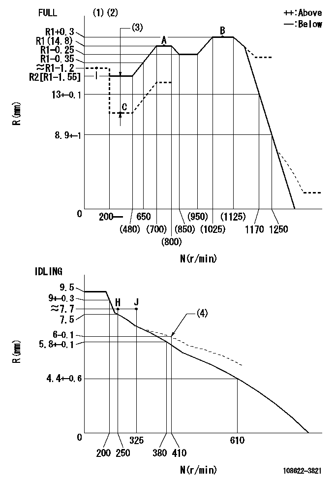
N:Pump speed
R:Rack position (mm)
(1)Torque cam stamping: T1
(2)Tolerance for racks not indicated: +-0.05mm.
(3)Boost compensator stroke: BCL
(4)Damper spring setting
----------
T1=AG29 BCL=1.6+-0.1mm
----------
----------
T1=AG29 BCL=1.6+-0.1mm
----------
Speed control lever angle
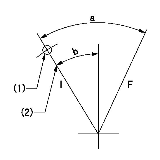
F:Full speed
I:Idle
(1)Use the hole at R = aa
(2)Stopper bolt setting
----------
aa=49.5mm
----------
a=35deg+-3deg b=19deg+-5deg
----------
aa=49.5mm
----------
a=35deg+-3deg b=19deg+-5deg
Stop lever angle
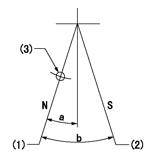
N:Pump normal
S:Stop the pump.
(1)Set the stopper bolt at rack position = approximately aa.
(2)At pump speed bb and rack position cc, set the stopper bolt.
(3)Use the hole above R = dd
----------
aa=19.3mm bb=0r/min cc=2.9+-0.3mm dd=35mm
----------
a=20deg+-5deg b=34deg+-5deg
----------
aa=19.3mm bb=0r/min cc=2.9+-0.3mm dd=35mm
----------
a=20deg+-5deg b=34deg+-5deg
0000001301

(1)Pump vertical direction
(2)Coupling's key groove position at No 1 cylinder's beginning of injection
(3)Pre-stroke: aa
(4)-
----------
aa=6.4+-0.03mm
----------
a=(50deg)
----------
aa=6.4+-0.03mm
----------
a=(50deg)
0000001901

A:Sealing position
B:Pre-stroke actuator
1. When installing the pre-stroke actuator on the pump, first tighten the installation bolts loosely, then move the actuator fully counterclockwise (viewed from the drive side).
Temporary tightening torque: 1 - 1.5 N.m (0.1 - 0.15 kgf.m)
2. Move the actuator in the clockwise direction when viewed from the drive side, and adjust so that it becomes the adjustment point of the adjustment value. Then tighten it.
Tightening torque: 7^9 N.m (0.7^0.9 kgf.m)
3. After prestroke actuator installation adjustment, simultaneously stamp both the actuator side and housing side.
----------
----------
----------
----------
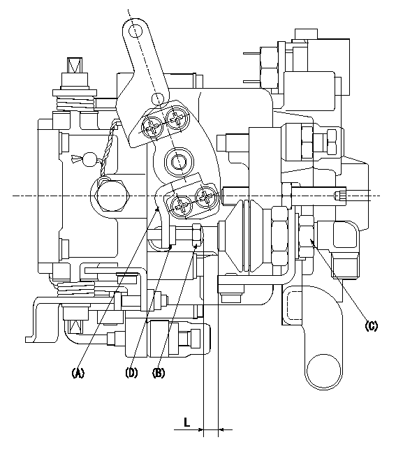
0000002201 RACK SENSOR
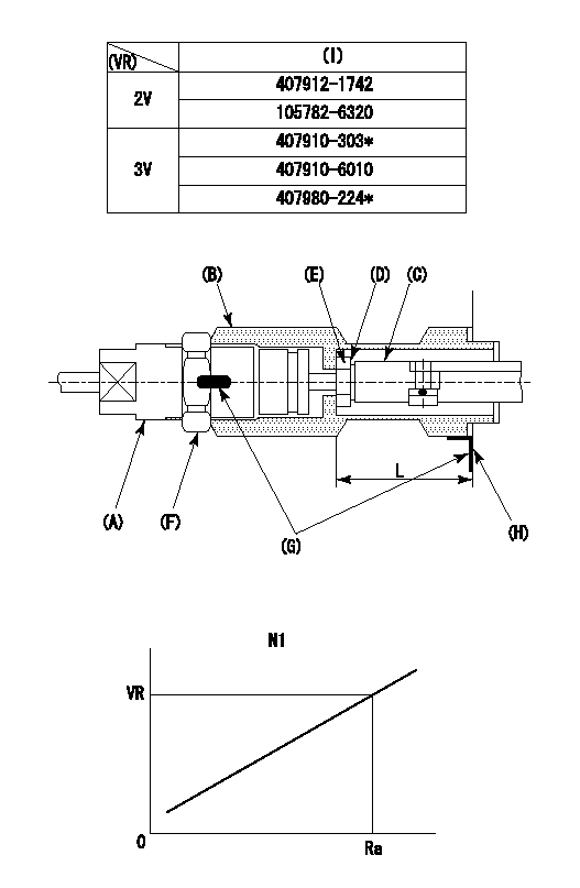
(VR) measurement voltage
(I) Part number of the control unit
(G) Apply red paint.
(H): End surface of the pump
Adjustment of the rack sensor (-0720)
1. Rack limit adjustment
(1)After mounting the joint (B), select the shim (D) so that the rack position is in the rack limit position.
(2)Install the rod (E) to the block (C).
(3)At the rack limit, set the distance between the pump end face and the rod (E) to L1.
2. Rack sensor
(1)Screw in the bobbin (A) until it contacts the joint (B).
(2)Fix the speed control lever at the full side and set the pump speed at N1.
(3)Adjust the depth that the bobbin (A) is screwed in so that the control unit's rack sensor output voltage is VR+-0.01 (V), then tighten the nut (F). (If equipped with a boost compensator, perform with boost pressure applied.)
(4)Apply red paint to both the joint (B) and the nut (F) join, and the joint (B) and the pump join. Output voltage VR +-0.01(V), speed N1, rack position Ra, rack sensor supply voltage 5+-0.01 (V)
----------
L=33.5+-0.1mm N1=1075r/min Ra=R1(14.8)+0.3mm
----------
----------
L=33.5+-0.1mm N1=1075r/min Ra=R1(14.8)+0.3mm
----------
0000002301 AIR CYLINDER
1. Air cylinder adjustment procedure
(1)Set the speed lever at idle.
(2)Temporarily set the clearance between the air cylinder (C) and the set bolt (B) to L1.
(3)Set the speed at N.
(4)Apply positive pressure P1 to the air cylinder (C).
(5)Gradually push out the set bolt (B).
(6)Tighten the nut (D) at the point where the rack position is Ra at speed N.
(7)Apply positive pressure P1 several times.
(8)Confirm that the lever returns to the idle position at positive pressure P2.
----------
L=(6)mm N=320r/min P1=392+98kPa(4+1kgf/cm2) P2=0kPa(0kgf/cm2) Ra=7.7+-0.1mm
----------
----------
L=(6)mm N=320r/min P1=392+98kPa(4+1kgf/cm2) P2=0kPa(0kgf/cm2) Ra=7.7+-0.1mm
----------
Information:
TECHNICAL INFORMATION BULLETIN March 05, 2003
Articulated Truck
Cold Planer
Landfill Compactor
Excavator
Motor Grader
Off-Highway Truck/Tractor
Quarry Truck
Track-Type Tractor
Underground Articulated Truck
Wheel Loader
Wheel Tractor
Wheel Tractor-Scraper D30C (05A)
PM-565 (3TK)
PM-565B (8GS)
836 (7FR)
5110B (AAA)
24H (7KK)
69D (9SS, 9XS)
73D (1GW)
769D (BBB, 5SS, 5TR)
773D (7ER, 7CS)
771D (BCA, 6JR, 6YS)
775D (6KR, 8AS)
D10R (3KR)
D9R (ABK, ACL, 7TL, 8BL)
AD40 II (1YZ)
AD45 (BKZ)
AE40 II (BLW, 1ZZ)
988F II (2ZR)
990 II (4FR)
834B (7BR)
844 (2KZ)
631E II (1AB1446-Up, 1NB)
631E (1AB1-1445)
631G (AWK)
633E II (2PS)
637E II (1FB532-Up)
637E (1FB1-531)
637G (AXT)
651E (4YR)
657E (5YR, 6PR, 6TR, 7KR)
Component Code: 1901SUBJECT: Flashing New Software When Electronic Control Module (ECM) or Injectors Are Replaced
PROBLEM:
There have been dealer reports of engine ECMs locking up when new software is being installed. Dealer staff may see a message on the service tool such as: "The ECM is not responding to the service tool. Error code 864256". The flashing will typically hang up after 88% complete. When you reconnect, ET will not be able to communicate. Messages you typically get: "The communication adapter was unable to connect to the ATA data link. Error # 441. The requested protocol is not compatible with an existing datalink." You may also see: "The software file and the ECM are not compatible. Process aborted ? Error Code: 147456."
The two new software part numbers are:
222-XXXX (needed when a 172-0802 ECM is replaced by a 156-7156 ECM)
214-YYYY (needed when new-style injectors are installed)
SOLUTION:
If you are considering performing Product Support Program PS50424 on one of the above-listed machines, you may want to delay the program until new software is released. New software will be released in the near future to resolve this issue. Once the flashfiles are in SIS Web, a follow-up TIB will announce the new software?s availability.
On machine engines that have an older ECM that fails (145-7808 or 172-0802), the current 156-7172 production ECM will be needed for parts service. This will require using one of the 222-XXXX flashfiles. To minimize the possibility of locking-up the ECM, the dealer service staff can do one of the following:
Flash the ECM before traveling to the job site. This will require a By-Pass harness.
Flash the ECM on the engine. A By-Pass harness is recommended. If a By-Pass harness is used, disconnect the machine wiring harness before flashing the engine ECM. Dealers report that this method reduces the number of lock-ups.
If the dealer does not have a By-Pass harness, one will have to be purchased or assembled. If a new 129-2018 Wiring Harness Assembly (By-Pass) is purchased, modifications are necessary. Instructions on how to modify a By-Pass harness (Method 1: Modify a By-Pass Harness) and assemble a By-Pass harness (Method 2: Assemble a By-Pass Harness) appear later in this TIB.
Note: When flashing engine ECMs, always download the file from SIS Web to the computer?s hard drive. The service person should then upload (flash) to the ECM from the computer?s hard drive. For a listing of all models affected and the current software, refer to REHS1385-02, "Introduction of New 3408E and 3412E Hydraulic Electronic Unit Injectors".
Method 1: Modify a By-Pass Harness
When flashing an on-engine ECM with the current files, Caterpillar recommends the use