Information injection-pump assembly
BOSCH
9 400 611 807
9400611807
ZEXEL
108622-3804
1086223804
HINO
220401621G
220401621g

Rating:
Service parts 108622-3804 INJECTION-PUMP ASSEMBLY:
1.
_
5.
AUTOM. ADVANCE MECHANIS
9.
_
11.
Nozzle and Holder
23600-2181C
12.
Open Pre:MPa(Kqf/cm2)
16.7{170}/27.5{280}
14.
NOZZLE
Include in #1:
108622-3804
as INJECTION-PUMP ASSEMBLY
Cross reference number
BOSCH
9 400 611 807
9400611807
ZEXEL
108622-3804
1086223804
HINO
220401621G
220401621g
Zexel num
Bosch num
Firm num
Name
Calibration Data:
Adjustment conditions
Test oil
1404 Test oil ISO4113 or {SAEJ967d}
1404 Test oil ISO4113 or {SAEJ967d}
Test oil temperature
degC
40
40
45
Nozzle and nozzle holder
105780-8250
Bosch type code
1 688 901 101
Nozzle
105780-0120
Bosch type code
1 688 901 990
Nozzle holder
105780-2190
Opening pressure
MPa
20.7
Opening pressure
kgf/cm2
211
Injection pipe
Outer diameter - inner diameter - length (mm) mm 8-3-600
Outer diameter - inner diameter - length (mm) mm 8-3-600
Overflow valve
134424-4120
Overflow valve opening pressure
kPa
255
221
289
Overflow valve opening pressure
kgf/cm2
2.6
2.25
2.95
Tester oil delivery pressure
kPa
255
255
255
Tester oil delivery pressure
kgf/cm2
2.6
2.6
2.6
RED3 control unit part number
407910-3
960
RED3 rack sensor specifications
mm
19
PS/ACT control unit part no.
407980-2
24*
Digi switch no.
33
Direction of rotation (viewed from drive side)
Right R
Right R
Injection timing adjustment
Direction of rotation (viewed from drive side)
Right R
Right R
Injection order
1-4-2-6-
3-5
Pre-stroke
mm
6.4
6.37
6.43
Beginning of injection position
Drive side NO.1
Drive side NO.1
Difference between angles 1
Cal 1-4 deg. 60 59.75 60.25
Cal 1-4 deg. 60 59.75 60.25
Difference between angles 2
Cyl.1-2 deg. 120 119.75 120.25
Cyl.1-2 deg. 120 119.75 120.25
Difference between angles 3
Cal 1-6 deg. 180 179.75 180.25
Cal 1-6 deg. 180 179.75 180.25
Difference between angles 4
Cal 1-3 deg. 240 239.75 240.25
Cal 1-3 deg. 240 239.75 240.25
Difference between angles 5
Cal 1-5 deg. 300 299.75 300.25
Cal 1-5 deg. 300 299.75 300.25
Injection quantity adjustment
Rack position
(14.6)
Vist
V
1.66
1.66
1.66
Pump speed
r/min
700
700
700
Average injection quantity
mm3/st.
182.5
180.5
184.5
Max. variation between cylinders
%
0
-2
2
Basic
*
PS407980-224*
V
2.2+-0.0
1
PS407980-224*
mm
4+-0.05
Injection quantity adjustment_02
Rack position
(7.1)
Vist
V
2.8
2.7
2.9
Pump speed
r/min
300
300
300
Average injection quantity
mm3/st.
21
20
22
Max. variation between cylinders
%
0
-15
15
PS407980-224*
V
V1+0.05+
-0.01
PS407980-224*
mm
6.3+-0.0
3
Remarks
Refer to items regarding the pre-stroke actuator
Refer to items regarding the pre-stroke actuator
0000001201
Pre-stroke
mm
6.4
6.37
6.43
Remarks
When the timing sleeve is pushed up
When the timing sleeve is pushed up
_02
Connector angle
deg.
11.5
11
12
Remarks
When the eccentric pin is tightened
When the eccentric pin is tightened
_03
Supply voltage
V
24
23.5
24.5
Ambient temperature
degC
23
18
28
Pre-stroke
mm
2.4
2.35
2.45
Output voltage
V
2.95
2.94
2.96
Adjustment
*
_04
Supply voltage
V
24
23.5
24.5
Ambient temperature
degC
23
18
28
Pre-stroke
mm
6.4
6.37
6.43
Output voltage
V
1.2
1
1.4
Confirmation
*
Remarks
Output voltage V1
Output voltage V1
_05
Supply voltage
V
24
23.5
24.5
Ambient temperature
degC
23
18
28
Output voltage
V
3.05
3.05
Confirmation of operating range
*
Test data Ex:
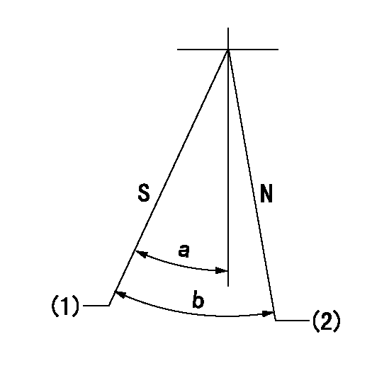
Speed control lever angle

N:Pump normal
S:Stop the pump.
(1)Rack position = aa
(2)Rack position bb
----------
aa=1mm bb=20mm
----------
a=34deg+-5deg b=37deg+-5deg
----------
aa=1mm bb=20mm
----------
a=34deg+-5deg b=37deg+-5deg
0000000901

(1)Pump vertical direction
(2)Coupling's key groove position at No 1 cylinder's beginning of injection
(3)Pre-stroke: aa
(4)-
----------
aa=6.4+-0.03mm
----------
a=(40deg)
----------
aa=6.4+-0.03mm
----------
a=(40deg)
0000001501

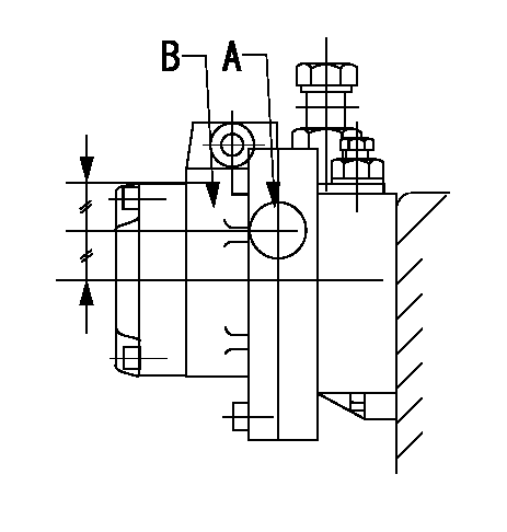
A:Sealing position
B:Pre-stroke actuator
1. When installing the pre-stroke actuator on the pump, first tighten the installation bolts loosely, then move the actuator fully counterclockwise (viewed from the drive side).
Temporary tightening torque: 1 - 1.5 N.m (0.1 - 0.15 kgf.m)
2. Move the actuator in the clockwise direction when viewed from the drive side, and adjust so that it becomes the adjustment point of the adjustment value. Then tighten it.
Tightening torque: 7^9 N.m (0.7^0.9 kgf.m)
3. After prestroke actuator installation adjustment, simultaneously stamp both the actuator side and housing side.
----------
----------
----------
----------
0000001701

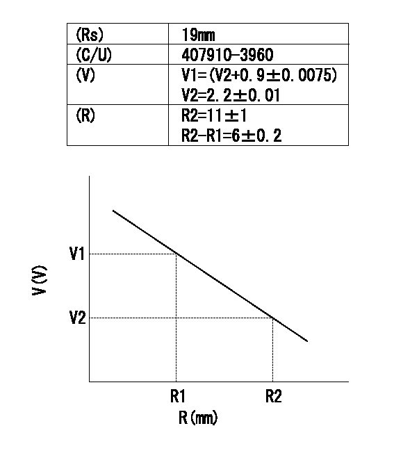
(Rs) rack sensor specifications
(C/U) control unit part number
(V) Rack sensor output voltage
(R) Rack position (mm)
1. Confirming governor output characteristics (rack 19 mm, span 6 mm)
(1)When the output voltages of the rack sensor are V1 and V2, check that the rack positions R1 and R2 in the table above are satisfied.
----------
----------
----------
----------
Information:
Starting From External Electrical Source
Always wear protective glasses when working with batteries.Do not allow the free end of booster cables to make contact with each other or touch the engine. This will help prevent sparks near the batteries.Batteries give off flammable fumes that can explode.Do not smoke when observing the battery electrolyte levels.Electrolyte is an acid and can cause personal injury if it contacts skin or eyes.
Be sure the main power switch is in the OFF position before attaching the booster cables to the engine being started. When using booster cables, be sure to connect in parallel: POSITIVE (+) to POSITIVE (+) and NEGATIVE (-) to NEGATIVE (-).Use only equal voltage for boost starting. The use of a welder or higher voltage will damage the electrical system.
Engines without engine-to-frame ground straps can be damaged by electrical discharge.To prevent electrical discharge damage, check to make sure there is an engine-to-frame ground strap. For engines which have the alternator connected to an engine component, the ground strap must connect that component to the frame.Some engines have starter-to-frame ground straps. But, many of these starters are not electrically grounded to the engine. They have electrical insulation systems. For this reason, the starter-to-frame ground strap may not be an acceptable ground.Connect one end of cable to the POSITIVE (+) (ungrounded) terminal of the battery on the engine being started. Connect the other end to the POSITIVE (+) terminal of the power source.Connect one end of the second cable to the NEGATIVE (-) terminal of the power source. Connect the other end to the frame of the engine to be started.Turn the start switch on and start the engine.Disconnect the cable from the frame first. Disconnect the other end from the NEGATIVE (-) terminal of the power source. Disconnect the cable from the POSITIVE (+) terminal of the battery. Disconnect the other end from the POSITIVE (+) terminal of the power source.