Information injection-pump assembly
ZEXEL
108622-3801
1086223801
Rating:
Cross reference number
ZEXEL
108622-3801
1086223801
Zexel num
Bosch num
Firm num
Name
108622-3801
INJECTION-PUMP ASSEMBLY
Calibration Data:
Adjustment conditions
Test oil
1404 Test oil ISO4113 or {SAEJ967d}
1404 Test oil ISO4113 or {SAEJ967d}
Test oil temperature
degC
40
40
45
Nozzle and nozzle holder
105780-8250
Bosch type code
1 688 901 101
Nozzle
105780-0120
Bosch type code
1 688 901 990
Nozzle holder
105780-2190
Opening pressure
MPa
20.7
Opening pressure
kgf/cm2
211
Injection pipe
Outer diameter - inner diameter - length (mm) mm 8-3-600
Outer diameter - inner diameter - length (mm) mm 8-3-600
Overflow valve
134424-4120
Overflow valve opening pressure
kPa
255
221
289
Overflow valve opening pressure
kgf/cm2
2.6
2.25
2.95
Tester oil delivery pressure
kPa
255
255
255
Tester oil delivery pressure
kgf/cm2
2.6
2.6
2.6
RED3 control unit part number
407910-3
960
RED3 rack sensor specifications
mm
19
PS/ACT control unit part no.
407980-2
24*
Digi switch no.
33
Direction of rotation (viewed from drive side)
Right R
Right R
Injection timing adjustment
Direction of rotation (viewed from drive side)
Right R
Right R
Injection order
1-4-2-6-
3-5
Pre-stroke
mm
6.4
6.37
6.43
Beginning of injection position
Drive side NO.1
Drive side NO.1
Difference between angles 1
Cal 1-4 deg. 60 59.75 60.25
Cal 1-4 deg. 60 59.75 60.25
Difference between angles 2
Cyl.1-2 deg. 120 119.75 120.25
Cyl.1-2 deg. 120 119.75 120.25
Difference between angles 3
Cal 1-6 deg. 180 179.75 180.25
Cal 1-6 deg. 180 179.75 180.25
Difference between angles 4
Cal 1-3 deg. 240 239.75 240.25
Cal 1-3 deg. 240 239.75 240.25
Difference between angles 5
Cal 1-5 deg. 300 299.75 300.25
Cal 1-5 deg. 300 299.75 300.25
Injection quantity adjustment
Rack position
(15.1)
Vist
V
1.59
1.59
1.59
Pump speed
r/min
700
700
700
Average injection quantity
mm3/st.
199
197
201
Max. variation between cylinders
%
0
-2
2
Basic
*
PS407980-224*
V
2.2+-0.0
1
PS407980-224*
mm
4+-0.05
Injection quantity adjustment_02
Rack position
(7)
Vist
V
2.8
2.7
2.9
Pump speed
r/min
280
280
280
Average injection quantity
mm3/st.
18.5
17.5
19.5
Max. variation between cylinders
%
0
-15
15
PS407980-224*
V
V1+0.05+
-0.01
PS407980-224*
mm
6.3+-0.0
3
Remarks
Refer to items regarding the pre-stroke actuator
Refer to items regarding the pre-stroke actuator
0000001201
Pre-stroke
mm
6.4
6.37
6.43
Remarks
When the timing sleeve is pushed up
When the timing sleeve is pushed up
_02
Connector angle
deg.
11.5
11
12
Remarks
When the eccentric pin is tightened
When the eccentric pin is tightened
_03
Supply voltage
V
24
23.5
24.5
Ambient temperature
degC
23
18
28
Pre-stroke
mm
2.4
2.35
2.45
Output voltage
V
2.95
2.94
2.96
Adjustment
*
_04
Supply voltage
V
24
23.5
24.5
Ambient temperature
degC
23
18
28
Pre-stroke
mm
6.4
6.37
6.43
Output voltage
V
1.2
1
1.4
Confirmation
*
Remarks
Output voltage V1
Output voltage V1
_05
Supply voltage
V
24
23.5
24.5
Ambient temperature
degC
23
18
28
Output voltage
V
3.05
3.05
Confirmation of operating range
*
Test data Ex:
Speed control lever angle
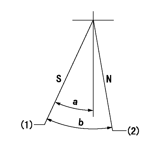
N:Pump normal
S:Stop the pump.
(1)Rack position = aa
(2)Rack position bb
----------
aa=1mm bb=20mm
----------
a=34deg+-5deg b=37deg+-5deg
----------
aa=1mm bb=20mm
----------
a=34deg+-5deg b=37deg+-5deg
0000000901

(1)Pump vertical direction
(2)Coupling's key groove position at No 1 cylinder's beginning of injection
(3)Pre-stroke: aa
(4)-
----------
aa=6.4+-0.03mm
----------
a=(40deg)
----------
aa=6.4+-0.03mm
----------
a=(40deg)
0000001501

A:Sealing position
B:Pre-stroke actuator
1. When installing the pre-stroke actuator on the pump, first tighten the installation bolts loosely, then move the actuator fully counterclockwise (viewed from the drive side).
Temporary tightening torque: 1 - 1.5 N.m (0.1 - 0.15 kgf.m)
2. Move the actuator in the clockwise direction when viewed from the drive side, and adjust so that it becomes the adjustment point of the adjustment value. Then tighten it.
Tightening torque: 7^9 N.m (0.7^0.9 kgf.m)
3. After prestroke actuator installation adjustment, simultaneously stamp both the actuator side and housing side.
----------
----------
----------
----------
0000001701

(Rs) rack sensor specifications
(C/U) control unit part number
(V) Rack sensor output voltage
(R) Rack position (mm)
1. Confirming governor output characteristics (rack 19 mm, span 6 mm)
(1)When the output voltages of the rack sensor are V1 and V2, check that the rack positions R1 and R2 in the table above are satisfied.
----------
----------
----------
----------
Information:
Voltage Regulator and Generator
Clean and Inspect
Before working inside the generator, make sure that the starter motor can not be activated by any automatic or manual signal.When the engine-generator is operating, voltages up to 600V are present in these areas near or on the regulator:1. The regulator terminal strip2. The excitation transformer terminal strip (self-excited generator only).Do not short these terminals to ground with any part of the body or any conductive material. Loss of life or injury could result from electrical shock or injury from molten metal.An electrical shock can be received from the regulator capacitor (C1) when the engine-generator is not in operation. To avoid possible injury, discharge the stored charge using an 100 ohm resistor across C1 terminals.
Electronic components in the regulator can be damaged during generator operation if contact is made between the part and ground.
If Moisture is allowed to remain in contact with an electrical winding, some of the moisture will eventually be absorbed. This will lower the resistance of the winding insulation. The insulation used on the windings of Caterpillar generators is moisture resistant, but constant exposure to moisture will gradually lower the insulation's resistance.Dirt can make the problem worse because it can hold the moisture in contact with the insulation. Salt (from sea air) can also make the problem much worse. This is because salt tends to absorb moisture from the air. When the salt and moisture combine, they make a good electrical conductor.Clean the voltage regulator and generator of dirt and debris. Use a brush to loosen accumulations of dirt and a vacuum system for removal. Use of compressed air is not recommended, because of moisture present in the form of condensate.Carbon tracking on insulators can be caused by dirt or loose connections. These carbon paths must be cleaned or the insulators replaced. Failure to correct a carbon tracking problem will eventually result in a short in the electrical circuit.Visually check for loose or broken wires and connections. Check the wires and connections on the regulator assembly. Check that all circuit boards are fully plugged in their sockets. Check all wires and connections in the generator. Make any necessary repairs to the wiring as required. Refer to the "Electric Set Generator Service Manual" for testing and adjusting or disassembly and assembly procedures.Space Heaters
The SR4 generator can operate in high humidity conditions without problems. However, problems can occur when the generator is idle and the surrounding air is warmer than the generator. Moisture can form on the windings and result in poor performance and even result in damage to the windings. Whenever the generator is not in use, insure that the space heaters are in operation.An external source of either 115 or 230 (200 v at 50 Hz) volts A.C. is required to operate the space heaters. Space Heater Connection to External Source H1, H2, H3, H4. Terminal Strip Terminals If 115 VAC source is available, connect
Have questions with 108622-3801?
Group cross 108622-3801 ZEXEL
Hino
108622-3801
INJECTION-PUMP ASSEMBLY