Information injection-pump assembly
BOSCH
9 400 612 090
9400612090
ZEXEL
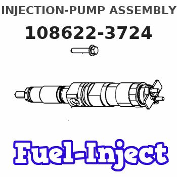
108622-3724
1086223724
HINO
220401343A
220401343a
Rating:
Service parts 108622-3724 INJECTION-PUMP ASSEMBLY:
1.
_
5.
AUTOM. ADVANCE MECHANIS
9.
_
11.
Nozzle and Holder
23600-3080A
12.
Open Pre:MPa(Kqf/cm2)
16.7{170}/27.5{280}
14.
NOZZLE
Include in #1:
108622-3724
as INJECTION-PUMP ASSEMBLY
Cross reference number
Zexel num
Bosch num
Firm num
Name
9 400 612 090
220401343A HINO
INJECTION-PUMP ASSEMBLY
P-6 * K 14CP TICS HD-TI6F TICS
P-6 * K 14CP TICS HD-TI6F TICS
Information:
1. Drain the cooling system.2. Remove bolt (2) and spacer (1). 3. Remove clip (3) that holds line (4) to the cylinder head. 4. Remove bolts (5) that hold fuel filter base and filter (6) to the cylinder head. 5. Fasten a chain and hoist to the cylinder head lifting brackets. Remove the bolts and nuts that hold the cylinder head. Remove the cylinder head. Weight of the cylinder head is 41 kg (90 lb.). 6. Remove cylinder head gasket (7).7. Check the condition of the cylinder head assembly before installation.Install Cylinder Head Assembly
1. Use a tap of the correct size to clean each threaded hole in the cylinder block for the cylinder head mounting bolts.2. Thoroughly clean the surface for the cylinder head gasket on the cylinder head assembly and cylinder block.
Be sure the gasket is positioned so that all coolant passages in the cylinder block can be seen through the gasket.
3. Put cylinder head gasket (1) in place on the studs in the cylinder block. 4. Put the cylinder head in position on the studs.5. Put clean engine oil on the bolt threads, and install the bolts that hold the cylinder head. 6. Tighten the bolts and nuts in the number sequence shown as follows:a. Tighten all bolts and nuts in number sequence to a torque of 45 N m (35 lb.ft.).b. Tighten all bolts and nuts in number sequence to a torque of 95 N m (70 lb.ft.).c. Again, tighten all bolts and nuts in number sequence to a final torque of 135 N m (100 lb.ft.). Retighten the cylinder head bolts and nuts after the engine has run under part load for approximately thirty minutes.a. If the bolts and nuts move before the correct final torque is reached, retighten every thing in the sequence again to the final torque of 135 N m (100 lb.ft.).b. If the bolts and nuts do not move before the correct final torque is reached, back each one off 30 to 60°, and retighten again, in the sequence shown, to the final torque. After all the bolts and nuts are retightened, check the first 10 positions to make sure they are tightened to the correct torque. 7. Install fuel filter base and filter (2) on the cylinder head with bolts (3).8. Install clip (4) that holds fuel line (5) to the cylinder head.9. Install the alternator bracket bolt and spacer in the cylinder head.End By:a. install fuel injection nozzle assembliesb. install fuel injection linesc. install inlet and exhaust manifoldd. install rocker shaft and push rods